Underground Storage Tank (UST) Technical Compendium about the 2015 UST Regulation
This compendium contains EPA’s interpretations and guidance about the 2015 underground storage tank (UST) regulation. Questions and answers are presented in these categories:
- Applicability
- Implementation
- State program approval
- Spill buckets, under dispenser containment sumps, containment sumps
- Secondary containment and interstitial monitoring
- Overfill protection
- Internal lining
- Walkthrough inspections
- Release detection
- Compatibility
- Release reporting
- Temporarily out of use facilities
- Partially excluded USTs
- Statistical inventory reconciliation
- Airport hydrant systems related to Department of Defense facilities
- Field-constructed tanks
- Emergency power generators
- Repairs to UST systems
Does the 2015 Federal UST Regulation Apply to You?
These questions and answers pertain to the 2015 revised federal UST regulation. Many states and territories (referred to as states) have state program approval from EPA. To find a list of states with state program approval, see State Underground Storage Tank (UST) Programs.
- If your UST systems are located in a state with state program approval, your requirements may be different from those described in this compendium. To find information about your state’s UST regulation, contact your implementing agency or visit its website. You can find links to state UST websites at Underground Storage Tank (UST) Contacts: States.
- If your UST systems are located in a state without state program approval, both the requirements discussed in this compendium and the state requirements apply to you. To make sure you are in compliance, you should follow the more stringent requirement.
- If your UST systems are located in Indian country, these questions and answers apply to you.
Applicability
Question: Are there any exemptions to the new regulation? Or are all USTs covered? For example, is there an exemption for a 1,000-gallon UST that is filled with heating oil? (Added: September 2015)
Answer: The 2015 UST regulation discusses partial and complete exclusions from applicability in 40 CFR 280.10 and definitional exemptions in 40 CFR 280.12 (see the definition of underground storage tank). See the UST regulations.
The definition of underground storage tank at 40 CFR 280.12 exempts tanks used to store heating oil for consumptive use on the premises where stored. So if this is a heating oil tank where the contents are used on the site where that tank is located, then EPA would not regulate this tank.
Note that state UST programs may regulate tanks that EPA excludes from regulation or exempts by definition.
Implementation
Effective Dates
Question: What are the effective dates for the requirements in the 2015 UST regulation? (Added: September 2015)
Answer: Generally, most requirements take effect October 13, 2018, which is 3 years after the effective date of the 2015 UST regulation. However, some requirements take effect on October 13, 2015, which is the effective date, or April 11, 2016, which is 180 days after the effective date. For example, the changes to compatibility take effect on October 13, 2015 and the secondary containment and under-dispenser containment requirements take effect April 11, 2016.
For details about implementation time frames, see page 41570 of the Federal Register containing the 2015 UST regulations (119 pp, 1.5 MB, About PDF).
In addition, EPA developed a brochure about implementation time frames.
State Program Approval
Question: States have three years to obtain SPA or redo their SPA application. I assume that gives them 3 years to write a rule. If the operation and maintenance requirements have to be initiated within 3 years of the effective date of the rule, does that give SPA states 3 years or 6 years to start O&M requirements? (Added: September 2015)
Answer: In states without state program approval (SPA) and in Indian country, the 2015 federal requirements apply according to time frames specified in the 2015 UST regulation.
In states with SPA, none of the 2015 federal requirements apply until a state adopts the federal requirements or if a state does not adopt the federal requirements, until EPA withdraws approval of SPA for that state. Owners and operators in states with SPA must continue to meet the state UST requirements.
States with SPA have 3 years from October 13, 2015, which is the effective date of the 2015 UST regulation, to revise their regulations and submit a revised SPA application. States can give owners the same amount of time to meet the state requirements as the federal regulation gives owners to meet the federal requirements (that is, 3 years after the effective date of the state regulation.) However, EPA expects that many states will impose shorter time frames than those in the federal requirements and may even impose more stringent requirements than the federal regulation.
State Program Approval
State Program Approval and Meeting the Operator Training Requirement
Question: Where in the preamble or regulation does it state that if the state meets the operator training requirement of the statute (and not the new regulation) they do not have to change their program requirements? (Added: September 2015)
Answer: EPA agreed very early in the federal regulatory development process that we would allow states to continue to implement their state-specific operator training programs according to EPA’s Grant Guidelines To States For Implementing The Operator Training Provision Of The Energy Policy Act Of 2005, despite differences that may exist with the operator training requirements in the 2015 UST regulation.
The revised SPA regulation at 40 CFR 281.39 – Operator Training, states: “In order to be considered no less stringent than the corresponding federal requirements for operator training, the state must have an operator training program that meets the minimum requirements of Section 9010 of the Solid Waste Disposal Act.” EPA developed operator training grant guidelines that meet Section 9010 of the Solid Waste Disposal Act. As long as a state meets the grant guidelines, it will be in compliance with § 9010 and, therefore, in compliance with 40 CFR 281.39. So a state with SPA would meet the operator training requirement even if it is different from the 2015 UST regulations.
Note that in non-SPA states, both state and federal operator training requirements apply.
Spill Buckets, Under Dispenser Containment Sumps, Containment Sumps
Visual Inspections To Comply With Spill Bucket And Sump Testing Requirements
Question: Can owners and operators use ASTM E3225-20 to meet requirements of the 2015 federal UST regulation for spill bucket and sump testing in 40 CFR § 280.35(a)(1)(ii)? (Added: March 2020)
Answer: No, owners and operators cannot use this ASTM standard to meet these testing requirements (ASTM E3225-20 Standard Practice for Performing a Liquid Test of Spill Prevention Equipment and Containment Sumps Used for Interstitial Monitoring of Piping by Visual Examination). Spill prevention equipment and containment sumps used for interstitial monitoring of piping must be tested to ensure the equipment is liquid tight by using vacuum, pressure, or liquid per 40 CFR § 280.35(a)(1)(ii). ASTM E3225-20 is a visually based standard practice that does not use vacuum, pressure, nor liquid procedures.
Question: Can states or territories with state program approval (SPA) at 40 CFR 281 allow their owners and operators to use ASTM E3225-20 to meet state regulatory requirements for spill bucket and sump testing? (Added: March 2020)
Answer: No, SPA states cannot allow their owners and operators to use ASTM E3225-20 to meet testing requirements for spill bucket and sumps. In order to be considered no less stringent than the 2015 federal UST regulation, states must require spill buckets and containment sumps used for interstitial monitoring of piping be tested for integrity. A visually based inspection does not constitute an integrity test per 40 CFR § 281.32(e).
Annual Walkthrough Requirements for Sumps
Question: The federal UST regulation requires an annual inspection of containment sumps according to 40 CFR 280.36(a)(1)(ii)(A). Does this include sump areas, that is the tank top and under dispenser areas, that:
- Are not used for interstitial monitoring; or
- Are only partially contained without bottoms; or
- Have no containment at all, with only dirt surrounding the submersible turbine pump (STP) or under the dispenser? (Added: April 2018)
Answer: Yes, the annual walkthrough inspection requirement generally applies to all operational sump areas. However, not all the specific requirements of the annual inspection are always applicable in each of those scenarios.
The specific requirements of the annual inspection according to 40 CFR 280.36(a)(1)(ii)(A) are to:
- Visually check for
- damage
- leaks to the containment area
- releases to the environment.
- Remove liquid or debris.
- For double-walled sumps with interstitial monitoring, check for a leak in the interstitial area.
So, for example, in a scenario where the STP or under dispenser areas have only partial containment sumps or no containment at all, removing liquid is not typically applicable; 40 CFR 280.36(a)(1)(ii)(A) indicates in contained sumps only.
Similarly, visually checking for damage does not typically apply directly to sump walls themselves when the sump is not used for interstitial monitoring because the function of the sump is not release detection. In those situations, an owner or operator is only required to visually check for damage to the proper operating condition of the equipment within the sump area, for example significant corrosion affecting proper STP operation, not necessarily to the sump or partial sump itself.
For containment sumps used for interstitial monitoring, the visual check applies directly to the sump itself. In those cases, the proper operating condition of the sump is to contain regulated substances and, therefore, the visual check is for any damage that makes the sump unable to contain regulated substances and not be liquid tight. The specific requirements to record and repair damage to containment sump tightness may vary depending on the operation and maintenance walkthrough inspection requirements of the implementing agency. For example, some states may require repair to achieve containment sump tightness up to or above the highest penetration point of the sump so that it meets the Petroleum Equipment Institute's (PEI) RP 1200-17 spill bucket and containment sump testing section 6 standards. EPA’s UST technical compendium discusses an example of low level sump testing under 40 CFR 280.35(a)(1)(ii)(C). In this example, EPA considers repair to achieve containment sump tightness to at least the height where a liquid level sensor will activate to be no less protective under 40 CFR 280.35(a)(1)(ii)(C).
Owners and operators in state program approval (SPA) states should check with their implementing agencies to determine applicable requirements, which may vary from EPA's determination in this area; see 40 CFR 281.32(f) General Operating Requirements.
Spill Bucket Testing on Stage I Vapor Recovery Lines
Question: If an owner has spill containment buckets installed on the Stage I fittings on the UST systems, would those be required to be tested every 3 years as well (or monitored monthly)? Or would they not require a test because they are not attached to the tank fill? (Added: September 2015)
Answer: 40 CFR part 280.20(c)(1)(i) only requires spill prevention equipment where the transfer hose is detached from the fill pipe. There is no requirement in the 2015 UST regulation for containment around a Stage I vapor recovery port. While it would be prudent to test any containment around the vapor recovery port, the 2015 UST regulation does not require owners and operators to perform this testing since the containment is not required by the UST regulation. Please note that the 2015 UST regulation requires testing of the containment if both the fill pipe and vapor recovery port are located in a single containment area.
Note that state UST programs may have more stringent requirements and may require testing of containment around Stage I vapor recovery ports.
Testing of Double-Walled Spill Buckets and Double-Walled Containment Sumps
Question: Are tank owners required to test at least once every three years double-walled spill buckets and containment sumps used for interstitial monitoring, if the interstitial space is periodically monitored and found to have integrity? (Added: September 2015; Modified November 2017)
Answer: Testing once every three years is not required if the integrity of both walls of a double-walled spill bucket or containment sump is periodically monitored. Owners and operators who check vacuum, pressure, or liquid interstitial integrity indicators on spill buckets at least every 30 days and containment sumps at least annually are considered to be periodically monitoring the integrity of both walls; see 40 CFR 280.35(a)(1)(i) and 280.36.
Every three years, owners and operators must test double-walled spill buckets and containment sumps if they choose not to periodically monitor the integrity of both walls; see 40 CFR 280.35(a)(1)(ii). Typically, a sensor in a dry interstice does not meet the requirement to periodically monitor the integrity of both walls. That means testing is required at least every three years for double-walled spill buckets and containment sumps with a sensor in a dry interstice.
According to 40 CFR 280.35(a)(1)(ii) A, B, or C, testing the interstice of spill buckets and containment sumps satisfies the every three year testing requirement if it is done according to:
- A code of practice developed by a nationally recognized association or independent testing laboratory, or
- Requirements developed by the manufacturer, or
- Requirements determined by the implementing agency to be no less protective of human health and the environment.
Owners and operators in State Program Approval (SPA) states should check with their UST implementing agencies to determine applicable requirements, which may vary from EPA's determination in this area; see 40 CFR 281.32(e) General Operating Requirements.
Containment Sump – Liquid Tightness
Question: EPA states that both new and existing containment sumps, when used for interstitial monitoring must be liquid tight. Does EPA require that containment sumps and under-dispenser containment (UDC) sumps be liquid tight on top, regardless of whether they have a lid or other cover? (Added: September 2015)
Answer: For UDC, the 2015 UST regulation at 40 CFR 280.20(f)(2) indicate that UDC must be liquid tight on its sides, bottom, and at any penetrations. This section does not indicate that UDC must be liquid tight on top.
For other containment sumps, 40 CFR 280.35(a)(1)(ii) indicates that the containment sump must be tested once every 3 years to ensure the equipment is liquid tight. There are no further details in the 2015 UST regulation for containment sump testing. Using a liquid test method to test a containment sump does not test the top or lid of the containment. In a vacuum test method, typically the lids are removed during the test.
Based on this information, EPA does not think containment sumps must be liquid tight on top, whether or not they have a lid or other cover.
Containment Sump – Dispenser Replacement and Under-Dispenser Containment Installation Requirements
Question: Are tank owners required to install UDC if only several components of the dispenser system are replaced, but not the entire dispenser system (for example a shear valve but not flexible connectors)? Or, are tank owners required to install UDC if any single component of the dispenser system is replaced? (Added: September 2015)
Answer: The 2015 UST regulation at 40 CFR 280.20(f) indicates that a dispenser system is considered new when both the dispenser and the equipment needed to connect the dispenser to the underground storage tank system are installed. That equipment may include check valves, shear valves, unburied risers or flexible connectors, or other transitional components that connect the dispenser to the underground piping. This means that the UDC requirement is not triggered until the dispenser and everything between the dispenser and the underground piping is installed.
Note that most states have already implemented their own requirements for secondary containment and UDC. The 2015 UST regulation primarily applies to owners and operators of UST systems in Indian country.
Containment Sump – UDC Installation with Sensor Monitoring
Question: Will the replacement of a dispenser at a site trigger the need to add an under-dispenser containment sump and sensor monitoring? (Added: December 2015)
Answer: If an existing dispenser and the equipment used to connect the dispenser to the underground piping are removed and replaced with a new dispenser, then under-dispenser containment is required for that dispenser; see 40 CFR 280.20(f).
EPA does not require owners and operators to add sensors for monitoring under-dispenser containment when UDC is required. Owners and operators may need to add sensors to UDC areas to meet the periodic monitoring requirement for sumps that cannot be visually inspected or to meet the piping interstitial monitoring requirement when piping is installed or replaced after April 11, 2016; see 40 CFR 280.20(f)(2).
Containment Sump – UDC Testing
Question: Are tank owners required to test all UDC or only UDC used for both secondary containment and interstitial monitoring of pipes? (Added: September 2015)
Answer: Periodic testing of containment sumps, including UDC, is required only when the containment sump is used for secondary containment of the piping and interstitial monitoring is used for release detection of that piping. The location of the interstitial monitoring device is not a factor in determining whether periodic testing is required. For example, owners and operators have UDC that is used as the secondary containment for piping where regulated substances can drain to another sump that is monitored with a sensor. In this case, UDC must meet the periodic testing requirement because it is used as part of secondary containment and interstitial monitoring of the piping.
Containment Sump – Testing for Systems with Double-Walled Piping
Question: Is containment sump testing required for double-walled piping systems that use sump sensors as a good management practice but rely on a method other than interstitial monitoring to meet the piping release detection requirement? (Added: December 2015)
Answer: No. The 2015 UST regulation does not require containment sump testing if the release detection method for the piping is something other than interstitial monitoring.
While EPA does not require this testing, some states may treat redundant release detection systems differently. Owners and operators should check with their UST implementing agencies to determine applicable requirements.
Containment Sump – Testing for Systems with Double-Walled Piping – Open and Closed to the UDC
Question: Do UDC sumps need to be tested once every 3 years if the double-walled piping is closed to the sump (i.e., the piping is double-walled throughout the dispenser and the containment sump is not used as part of the secondary containment of the piping)? (Added: September 2015)
Answer: The requirement to test sumps, or have double-walled sumps with periodic monitoring, hinges on whether that sump is used as part of the piping secondary containment when interstitial monitoring is used as release detection for the piping. The requirement to test the sump is independent of whether the sump is open or closed or whether sensors reside in that sump or somewhere else. And it applies to any containment sump used for piping interstitial monitoring, independent of whether the containment sump is old or new.
Any sump used as part of the secondary containment system that is interstitially monitored must either be double-walled with periodic monitoring of the space between the sump walls or be tested once every 3 years.
Question: If the double-walled piping is open under the dispenser allowing a leak to drain into the dispenser sump or the submersible turbine pump (STP) sump, then do the UDC sumps and the STP sump have to be tested once every 3 years? (Added: September 2015)
Answer: For the question about closed piping under dispensers, in this case, the under-dispenser containment does not need to be tested because the UDC is not part of the piping secondary containment where interstitial monitoring is used.
If the outer wall of the double-walled piping is open in the UDC, or ends at the UDC wall, then the UDC would be considered secondary containment for the single-walled piping in the UDC, independent of whether the UDC was open or closed to the STP sump. In this case, the UDC is part of the secondary containment and interstitial monitoring for the piping, and therefore would have to be tested once every 3 years, or be double-walled with periodic monitoring of the space between the walls.
Containment Sump – Testing for Systems with Single-Walled Piping
Question: Suppose there is single-walled piping in a UDC sump leading up to the dispenser, below the shear valve, and the single-walled piping is connected by single-walled flex connector to double-walled piping.
Does the single-walled piping have to meet the secondary containment and interstitial monitoring requirement?
Does the UDC have to meet the 3-year testing requirement? (Added: March 2017)
Answer: Yes, to both questions. According to the 2015 federal UST regulation, all piping installed or replaced after April 11, 2016 must meet the secondary containment and interstitial monitoring requirement. EPA considers the UDC as secondary containment for the single-walled piping, including the single-walled flex connector, beneath the shear valve. According to 40 CFR 280.43(g), owners must monitor the UDC by interstitial monitoring as the primary method of release detection.
In this case, the UDC is part of the secondary containment and interstitial monitoring for the single-walled piping; it must be tested once every 3 years or be double-walled with periodic monitoring of the space between the walls.
Note that most states have already implemented their own requirements for secondary containment and UDC. The 2015 federal UST regulation primarily applies to owners and operators in Indian country.
Containment Sump – Test Procedures
Question: What procedures can be used to test single-walled containment sumps? Is there a procedure that tests containment sumps, does not require filling the containment sump with water to 4 inches higher than the highest penetration in the sump, and is acceptable to EPA? (Added: May 2017; Modified June 2018; Modified March 2020)
Regulatory requirement
Unless the sump is double-walled and the integrity of both walls is periodically monitored, 40 CFR 280.35(a)(1)(ii) requires containment sumps used for interstitial monitoring of piping be tested at least once every three years to ensure the equipment is liquid tight by using vacuum, pressure, or liquid testing. Options for conducting the test include: (A) requirements developed by the manufacturer, (B) a code of practice developed by a nationally recognized association or independent testing laboratory, (C) requirements developed by the implementing agency determined to be no less protective of human health and the environment than (A) or (B).
Answer: As noted above, EPA allows three options for testing containment sumps, also referred to as sumps. Below is information about each option.
Requirements Developed By Sump Manufacturer
EPA is not aware of any manufacturers of single-walled containment sumps who provide procedures on how to test their sumps.
Code Of Practice
EPA is aware of only one code of practice that provides procedures to test a sump using vacuum, pressure, or liquid. That code of practice is Petroleum Equipment Institute Recommended Practice (PEI RP) 1200-19, which provides two procedures for testing containment sumps. The original procedure requires testing the sump by filling it with water to 4 inches above the highest penetration. In 2019, PEI updated RP 1200 to provide another procedure for testing the sump at a lower liquid level if certain conditions are met. Since both procedures are contained within a code of practice developed by a nationally recognized association and the procedures test the sump hydrostatically, EPA determined these testing procedures are acceptable to meet the requirement to test the containment sump for liquid tightness.
Alternative Test Procedures – EPA Low Liquid Level Testing
Before PEI revised RP 1200 to include a low liquid level testing procedure, EPA was aware that in some situations, such as for certain older systems, testing to 4 inches above the highest penetration may create unusual challenges and unintended consequences. These include:
- It could be difficult to access the sump, requiring the dispenser be removed in order to do the testing.
- The challenges and costs of testing above penetration fittings may lead some owners to abandon their interstitial monitoring and move to a different and possibly less protective release detection method.
- The increased costs incurred for testing to the higher level may serve as a disincentive for owners to upgrade existing systems to include double-walled piping with interstitial monitoring and containment sumps.
While testing to a level less than 4 inches above the highest penetration may be less protective than testing at a higher liquid level, if included with conditions similar to those specified in PEI RP 1200, the implementing agency may be able to determine that testing at a lower level is as protective as testing at a higher liquid level. This example discusses what EPA considers to be no less protective under 40 CFR 280.35(a)(1)(ii)(C).
Example
- A liquid level sensor is mounted at the lowest point in the sump and a periodic test is performed by adding liquid to a point that will ensure activation of the sensor; and
- The pump automatically shuts off when liquid activates the sensor, or
- The dispenser automatically shuts off when liquid activates the sensor, and the facility is always staffed when the pumps are operational.
Low Liquid Level UST Containment Sump Testing Procedures for conducting this alternate test at facilities where EPA is the implementing agency.
Sample Form For Documenting Compliance With Low Liquid Level UST Containment Sump Testing Procedures (DOCX)(2 pp, 36 K, June 2018)
Additional Alternative Test Procedures
In addition, EPA is aware of other containment sump testing procedures that are not provided by the sump manufacturer and are not incorporated into a code of practice. Nevertheless, these procedures test the liquid tightness of the sump using vacuum, pressure, or liquid.
EPA determined sump tests meeting the criteria below are no less protective of human health and the environment under 40 CFR 280.35(a)(1)(ii)(C). It is acceptable to use them for sump tests in instances when EPA is the implementing agency.
- The sump is tested for liquid tightness using vacuum, pressure, or liquid.
- Equipment and procedures for the sump test can detect a leak of 0.1 gallons per hour with a probability of detection of at least 95 percent with a probability of false alarm of no more than 5 percent.
- The test method has been evaluated by an independent testing laboratory, consulting firm, not-for-profit research organization, or education institution using an applicable test procedure developed by EPA, and the test procedure is appropriate for the type of release detection technology being evaluated. You may obtain the test procedures at EPA’s underground storage tank website www.epa.gov/ust/standard-test-procedures-evaluating-various-leak-detection-methods.
To demonstrate their sump test meets the above criteria, manufacturers may request the National Work Group on Leak Detection Evaluation (NWGLDE) review their evaluation. NWGLDE lists those sump tests that meet the criteria; see Secondary and Spill Containment Test Methods at nwglde.org/methods/sec_spill_cont.html.
UST Sump Test Water Characterization and Disposal
Question: Because petroleum constituents may be present, is the used test water considered a hazardous waste under 40 CFR Part 261, Identification and Listing of Hazardous Waste, (RCRA Subtitle C)? (Added: May 2017)
Answer: Under the Resource Conservation and Recovery Act (RCRA), Subtitle C, a material must first be a solid waste as described under 40 CFR 261.2 before it can be a hazardous waste. As long as the test water is suitable for reuse and is continuing to be reused, it is not considered a waste. When it is to be disposed, it becomes a solid waste and must be evaluated to determine whether it is a hazardous waste.
Once the sump test water will be disposed, the test water will be a hazardous waste if it exhibits any of the characteristics of hazardous waste described in 40 CFR 261.21-24. With the test water, the most likely characteristics that could apply are the toxicity characteristic (TC) in 40 CFR 261.24 and ignitability characteristic in 40 CFR 261.21.
- Toxicity characteristic: The chemical benzene, often found in petroleum products, is the constituent most likely to be found in UST sump test water in concentrations equal to or greater than the TC regulatory value, which for benzene is 0.5 mg/l. Thus approximately 0.007 ounces of benzene in 100 gallons of test water would exceed the TC limit. Note: The water solubility of benzene at 23.5 degrees C is 0.188 percent, or 1880 ppm. While gasoline has typically contained approximately 1 percent benzene, in 2011 EPA required benzene to be limited to 0.62 percent; see entry 1094 of the Merck Index, 12th Ed., 1996, and Gasoline Mobile Source Air Toxics.
- Ignitability characteristic: If a representative sample of the sump test water exhibits a flash point below 140 degrees F at the point of generation or during the course of its management, it would be an ignitable hazardous waste. Note: Pure benzene has a closed cup flash point of 12 degrees F; see entry 1094 of the Merck Index, 12th Ed., 1996.
- Gasoline is more likely than diesel fuel, kerosene, or heating oil to be hazardous for benzene or flash point. Kerosene has a flash point of 150-185 degrees F; see entry 5305, Merck Index, 12th Ed, 1996.
Question: What procedures can be used to determine if the test water is hazardous waste under RCRA Subtitle C? (Added: May 2017)
Answer: 40 CFR 262.11, Standards Applicable to Generators of Hazardous Waste, requires generators to employ one of two procedures to determine whether a solid waste is a hazardous waste:
- Analytical testing: With respect to the sump test water, the relevant tests for benzene are: EPA Method 1311/8260 or 1311/5030/8015 or 1311/5030/8021 to determine if there is enough benzene in the test water that it fails for toxicity, and EPA Methods 1010A or 1020B to determine if the test water fails for ignitability. Toxicity characteristic leaching procedure, or TCLP, is the method used for determining whether a waste exhibits the toxicity characteristic; see 40 CFR 262.11. Note the TCLP test considers the solids content of the test water. More information about these laboratory test methods are available in EPA’s SW-846 Compendium.
- Generator knowledge: Generators may apply knowledge of the hazard characteristics of the waste in light of the materials or the process used to generate the waste. The key to using a knowledge of process is that it should be scientifically defensible and capable of reliably and accurately determining whether the waste is hazardous, particularly for non-hazardous determinations. Because only a very small amount of benzene needs to be present in order for the test water to be TC hazardous (approximately 0.007 ounces of benzene in 100 gallons of water), a knowledge of process evaluation is in all likelihood incapable of ascertaining that the test water is non-hazardous, but it certainly could be used to determine the water to be hazardous (based on the water solubility of benzene and its presence in gasoline). Appropriate knowledge of materials and process for a waste stream like the test water could include information such as:
- The process that generated the waste (that is, the fact that this process brings water into contact with gasoline, which contains benzene).
- Observation of visible free petroleum in the test water, since the test water is likely to fail analytical testing if visible petroleum is present.
- Past sampling results of prior test water generated under similar conditions.
- Basic physical and chemical knowledge about likely waste constituents.
Question: Is the test water exempt from the hazardous waste requirements via the exemption in 40 CFR 261.4 (b)(10)? This exemption states that the following solid wastes are not hazardous wastes:
40 CFR 261.4(b)(10): “Petroleum-contaminated media and debris that fail the test for the Toxicity Characteristic of §261.24 (Hazardous Waste Codes D018 through D043 only) and are subject to the corrective action regulations under part 280 of this chapter.” (Added: May 2017)
Answer: The test water does not qualify for this exemption from the hazardous waste requirement for several reasons. First, the test water is not consistent with the term media or debris as defined in 40 CFR 261 and 268.2(g). That is, the water being discarded has been used as a product for testing sump integrity and is not ambient media that has been contaminated by an outside source. Second, even if it were media or debris that fails the toxicity characteristics of 40 CFR 261.24, the test water is not subject to the corrective action regulation under 40 CFR 280. Water used to test multiple sumps may pick up petroleum constituents but would not generally require reporting under the UST regulation, unless there is an indication of a release from the UST system. Therefore, sump test water does not meet the requirements for the exemption. Federal Register, Vol 58, No 28 (332 pp, 83 MB, About PDF).
Question: Is the test water exempt from the hazardous waste requirements if it is sent for reclamation per 40 CFR 261.2(c)(3)? (Added: May 2017)
Answer: The regulation at 40 CFR 261.2(c)(3) exempts from regulation off-specification commercial chemical products that are legitimately reclaimed to produce fuels. EPA has interpreted this exemption to include off-specification fuel materials such as fuel and water mixtures in a November 2016 letter (2 pp, 390K, About PDF).
This exemption could apply to the test water, if the test water contains enough fuel such that fuel could be legitimately reclaimed if the test water is sent to a fuel recycling facility for recovery.
Question: If the water is reused multiple times and transferred from one sump to another, when does a hazardous characterization have to occur? (Added: May 2017)
Answer: If the testing contractor or UST facility owner and operator can and does reuse the test water to perform testing at another facility, then the test water is not a waste at that point. A testing contractor or UST facility owner and operator could potentially reuse the water over and over again, especially if the test water is filtered in between uses to remove any free or dissolved petroleum. When the tester decides not to reuse the water, it then becomes a waste, must be characterized, and either properly disposed or determined if it can be reclaimed as discussed in question above about reclamation.
Question: If the test water is characterized as hazardous waste, how must it be properly managed? (Added: May 2017)
Answer: Possible options include legitimate reclamation of the test water or disposing of it according to prescribed RCRA regulations.
- See question and answer above for possible reclamation options.
- Possible disposal options include:
- If the test water is not ignitable, it may be acceptable to dispose of it via the sanitary sewer. Approval from the local sewer authority is generally required and it is highly recommended that you check with your state, tribal, and local authorities for rules or other restrictions regarding such a disposal method.
- You may drum and store the test water properly until a hazardous waste hauler picks it up according to the hazardous waste generator regulations which specify accumulation time and management standards depending on how much hazardous waste is generated in a calendar month; see EPA's hazardous waste generator website for more info. Check with your state, tribal, and local authorities for the applicable requirements for hazardous waste stored on site by generators and also to determine if there are licensing requirements for hazardous waste haulers in your jurisdiction.
- You may filter the test water through an oil-water separator and properly dispose of the oil and water. Check with your state, tribal, and local authorities for requirements regarding disposal of the oil and water from the oil-water separator. It is possible that even after the water is filtered, it may contain enough benzene to be considered hazardous waste.
Question: If the test water is not characterized as being a hazardous waste, how can it be properly disposed? (Added: May 2017)
Answer: Even where the water is non-hazardous under the RCRA regulations, the testing contractor or UST facility owner and operator should check with state, tribal, and local authorities regarding applicable requirements for disposal, including disposal to the sanitary sewer or other safe waste management practice.
Question: Who becomes the generator for the test water when it is no longer usable and becomes a waste? (Added: May 2017)
Answer: This depends on when and where the test water becomes a waste. If the test water is used just once prior to being disposed, then the facility where the test is conducted is the generation site. Under the RCRA hazardous waste generator requirements, where more than one party’s actions contribute to a waste being generated, all parties are subject to joint and several liability as generators – they are co-generators. For example, the testing contractor is a generator under 40 CFR 262.10 because his actions produce the waste test water, and the owner and operator of the facility is a generator because they own the equipment from which the waste is generated. Joint and several liability dictates that both generators are responsible for ensuring compliance with applicable hazardous waste requirements. However, EPA prefers and even encourages one party to assume and perform the duties and responsibilities of generator on behalf of all parties, as appropriate. EPA recommends that co-generators specify via a contract who is responsible for compliance with hazardous waste and disposal requirements.
Question: What if it is not determined whether the test water will be reused until after the test water is returned to the testing contractor’s home site? (Added: May 2017)
Answer: If the test water is returned to the testing contractor’s home site and it is then determined the test water will not be reused, the testing contractor is the sole generator and solely responsible for evaluating and properly managing the waste.
For additional information, see EPA’s Waste Analysis at Facilities that Generate, Treat, Store and Dispose of Hazardous Waste – Final: A Guidance Manual.
Tank Collars Connected to Sumps
Question: When using a double-walled sump with interstitial monitoring, does the collar connecting the sump to the tank top surface also have to be double-walled? (Added: December 2017)
Answer: Yes; the collar connecting the sump to the tank top surface has to be double-walled. The interstice or interstitial communication must be continuous for the entire containment area.
Secondary Containment and Interstitial Monitoring
Secondary Containment and Interstitial Monitoring
Question: After April 2016 new installations must use interstitial monitoring for release detection. Can locations installed prior to April 2016 that have all components necessary to perform interstitial monitoring use another form of release detection? For examples, could double-walled tanks use SIR or CSLD? Could double-walled piping use 3 gph LLDs and annual line tightness testing? (Added: September 2015)
Answer: The 2015 federal UST requirement for secondary containment and interstitial monitoring only applies to tanks and piping installed after April 11, 2016.
Owners and operators who install petroleum tanks on or before April 11, 2016 may choose to use any of the release detection options listed in Subpart D of the UST regulation. They are not restricted to only interstitial monitoring.
Owners and operators who install piping on or before April 11, 2016 may choose to use any of the release detection options listed in Subpart D of the UST regulations. They are not restricted to only interstitial monitoring.
Note that some states already have secondary containment requirements in place, so to determine their requirements, owners and operators need to check with the state in which the USTs reside.
Secondary Containment and Remote Fill Pipes
Question: Does EPA think that the secondary containment and corrosion protection requirements apply to remote fill pipes because they do not routinely contain regulated substances? (Added August 2017)
Answer: EPA has determined that the secondary containment and corrosion protection requirements do not apply to remote fill pipes.
EPA’s 2015 UST regulation defines piping as “a hollow cylinder or tubular conduit that is constructed of non-earthen materials”. Remote fill pipes meet the definition of piping; however, EPA does not consider fill pipes, in general, as components that routinely contain product and so they do not require the same treatment as other piping which requires secondary containment along with interstitial monitoring and corrosion protection.
EPA’s Energy Policy Act grant guidelines for secondary containment were more explicit in defining piping, specifically excluding fill pipes from the definition. The secondary containment grant guidelines defined piping this way: “For purposes of these guidelines, piping is the hollow cylinder or the tubular conduit constructed of non-earthen materials that routinely contains and conveys regulated substances from the underground tank(s) to the dispenser(s) or other end-use equipment. Such piping includes any elbows, couplings, unions, valves, or other in-line fixtures that contain and convey regulated substances from the underground tank(s) to the dispenser(s). This definition does not include vent, vapor recovery, or fill lines.”
EPA’s response to comments and the preamble to the 2015 UST regulations discuss situations in which secondary containment may not be necessary, such as with safe suction piping. The preamble states, “Safe suction piping operates at less than atmospheric pressure, slopes towards the UST so regulated substances drain to the UST if suction is lost, and has only one check valve located close to the suction pump”.
EPA has determined remote fill pipes generally meet the same characteristics as safe suction piping, and, therefore, have a similar low risk of release. As a result, EPA thinks that the release detection, corrosion protection, and secondary containment and interstitial monitoring requirements for piping in the federal UST regulation do not apply to remote fill pipes.
Interstitial Monitoring
Question: Do new or replacement fiberglass clad steel tanks need interstitial monitoring? (Added: September 2015)
Answer: The 2015 UST regulation requires all underground storage tanks and piping to have secondary containment and interstitial monitoring when installed or replaced after April 11, 2016. A fiberglass clad steel tank is not considered secondarily contained unless it has two steel walls. However, a steel tank jacketed with fiberglass is a secondarily contained tank.
Note that some states already have secondary containment and interstitial monitoring requirements in place, so to determine their requirements, owners and operators need to check with the state in which the USTs reside.
Piping Run Replacement and Secondary Containment
Question: When is secondary containment required when a piping run is replaced? (Added: March 2017)
Answer: After April 11, 2016 when 50 percent or more of the piping connected to a single tank is removed and replaced, the piping must have secondary containment.
40 CFR 280.12 Replaced means:…(2) For piping – to remove 50 percent or more of piping and install other piping, excluding connectors, connected to a single tank. For tanks with multiple piping runs, this definition applies independently to each piping run.
40 CFR 280.20 Performance standards for new UST systems…tanks and piping installed or replaced after April 11, 2016 must be secondarily contained and use interstitial monitoring in accordance with 40 CFR 280.43(g)…For cases where the piping is considered to be replaced, the entire piping run must be secondarily contained.
Secondary Containment or Piping Run Replacements with More Than One STP
Question: How do I apply the requirement for secondary containment when 50 percent of a piping run is replaced when there is more than one STP (either manifolded or in line)? (Added: December 2015; Modified: March 2017)
Answer: Each UST site may have unique characteristics that require implementing agencies to think about how to apply the piping run definition. As a general rule of thumb, EPA considers all piping downstream from a single submersible turbine pump (STP) to be part of a single piping run. Likewise, all piping upstream from the suction pump to the storage tank would be part of a single piping run.
The examples and graphics below help explain this.
Example 1: If an owner and operator have two STPs on a single tank where piping leaves each STP and then joins together at some later point, these are two piping runs with some of the same piping attributed to each piping run. Changes to the piping that is shared by both piping runs will impact the calculation of the 50 percent replacement and secondary containment requirements for each entire piping run. If the secondary containment is only triggered for one of the piping runs, then secondary containment is only required for that one entire piping run.
Example 1A

- 75 feet of piping run 1 is replaced, beginning at the STP and ending 15 feet into the shared piping run c.
- This equals more than 50 percent of the 140 feet total length of piping run 1; therefore, all of piping run 1 must be replaced and have secondary containment. The piping run begins at the STP and ends at the dispensers and equals 140 feet.
- Because the piping segment that is shared by both piping runs is now required to be replaced, this may impact piping run 2.
- The 80-foot replacement of shared piping run c, is greater than 50 percent of the 140 feet total length of piping run 2; therefore, all of piping run 2 must be replaced and have secondary containment.
Example 1B

- 75 feet of shared piping run c is replaced.
- This is greater than 50 percent of the 140 feet total length of piping run 1 and greater than 50 percent of the 140 feet total length of piping run 2; therefore, all of piping run 1 and all of piping run 2 must be replaced and have secondary containment.
Example 1C

- 75 feet of shared piping run c is replaced.
- This is greater than 50 percent of the 140 feed total length of piping run 1; therefore, all of piping run 1 must be replaced and have secondary containment.
- Because the piping segment that is shared by both piping runs is now required to be replaced, this may impact piping run 2.
- The total length of piping run 2 is 170 feet. The 80-foot replacement of shared piping run c does not equal 50 percent of the length of piping run 2; therefore piping run 2a, from the STP to the junction where shared piping begins, does not have to be replaced and may remain single walled.
Example 1D

- 50 feet of shared piping run c is replaced.
- Because 50 feet is less than 50 percent of the total of either piping run 1 or piping run 2, no secondary containment is required on the replaced section of piping.
Question: How do I apply the piping run definition if the piping has both a suction pump and a pressurized pump? (Added: December 2015; Modified: March 2017)
Answer:
Example 2: If an owner and operator has a suction piping system from the tank to an intermediate storage tank, followed by a pressurized piping system from the intermediate tank to the end of the piping. EPA considers these are two piping runs.

- The suction piping run 1 passes from the tank to the suction pump.
- The pressurized piping run 2 passes from the STP to the dispensers.
Example 3: If an owner and operator has an STP with pressurized piping beginning at the tank followed by a suction pump at some point in the piping, these are two piping runs. For this configuration, there needs to be some intermediate storage from which the suction pump draws the regulated substance. This scenario assumes the pressurized piping pumps regulated substance to an intermediate storage area where it is then drawn using a suction system. EPA considers these are two piping runs.

- The pressurized piping run 1 passes from the STP to the intermediate storage tank.
- The suction piping run 2 passes from the intermediate tank to the suction pump.
Note that in all of these examples, the UST regulations do not include aboveground piping.
Day Tanks
Question: Do day tanks that are considered underground storage tanks need secondary containment if they are less than 1,100 gallons? (Added: December 2015)
Answer: Generally, yes. Day tanks that are part of a regulated UST system installed after April 11, 2016 must be secondarily contained and have interstitial monitoring; see 40 CFR 280.20. If day tanks were installed prior to October 13, 2015, owners and operators have until October 13, 2018 to begin meeting the release detection requirements in subpart D of the 2015 UST regulation. There are two exceptions:
- An owner and operator has an aboveground day tank associated with an airport hydrant system or field-constructed tank where the overall system meets EPA’s definition of UST system. In this case, the aboveground day tank is partially excluded from most of the 2015 UST regulation, including secondary containment and interstitial monitoring; see 40 CFR 280.10(c).
- The definition of underground storage tank in 40 CFR 280.12 excludes (1) farm or residential tanks of 1,100 gallons or less capacity used for storing motor fuel for noncommercial purposes and (2) tanks used for storing heating oil for consumptive use on the premises where stored.
Secondary Containment Requirements for Interstitial Connection Tube
Question: In a double-walled piping system where the interstitial space is connected around a pipe fitting in the UDC via a single-walled jumper connection tube, would the jumper connection tube require secondary containment? Would the UDC need to be periodically tested to provide secondary containment for the jumper connection tube? (Added: March 2017)
Answer: The jumper connection tube connecting the secondary containment interstice around a pipe fitting in the UDC does not require secondary containment. The UDC, therefore, would not have to be periodically tested as a means of secondary containment for the interstice jumper connection tube.
However, according to the 2015 federal UST regulation, all piping installed or replaced after April 11, 2016 must meet the secondary containment and interstitial monitoring requirement. If single-walled piping is present, EPA considers the UDC as secondary containment for the single-walled piping, including the single-walled flex connector, riser, or tee beneath the shear valve. In this case, the UDC is part of the secondary containment and interstitial monitoring for the single-walled piping and, therefore, it must be tested once every 3 years or be double-walled with periodic monitoring of the space between the walls.
Overfill Protection
Overfill Prevention Inspections
Question: Are tank owners required to pull the automatic shut off device out of the tank during the periodic overfill inspection process? (Added: September 2015)
Answer: The 2015 UST regulation in 40 CFR 280.35(a)(2) indicates the inspection must ensure overfill prevention equipment is set to activate at the correct level and will activate when regulated substance reaches that level. The 2015 UST regulation does not require the automatic shutoff device be removed during the inspection. The inspection criteria are listed in 40 CFR 280.35 (a)(1)(ii)(A-C).
Overfill Prevention Inspections – Multiple Devices
Question: Some UST systems use two or more of the overfill prevention options listed in the federal UST regulation. Do owners and operators have to inspect all overfill devices used on the tank or only the one being used to meet the overfill prevention requirement? (Added: December 2015)
Answer: From EPA’s perspective, only the method of overfill prevention being used to meet the UST regulation must meet the overfill prevention inspection requirement in 40 CFR 280.35. One note: owners and operators must ensure any secondary overfill methods they use do not interfere with the primary method they use to meet the overfill prevention requirement. You should not use an automatic shutoff device if the UST receives pressurized deliveries.
Some states may require inspections of all overfill prevention equipment used on the UST system. Please check with implementing agencies to determine their requirements.
Ball Float Valves
Question: If a tank owner and operator is using a high level alarm set to 90 percent capacity to meet the overfill prevention requirements, can the tank owner still install a ball float valve after October 13, 2015 set at a higher level as a second line of defense? (Added: December 2015)
Answer: Owners and operators may not use flow restrictors in vent lines (also called ball float valves) to meet the overfill prevention requirement when overfill prevention equipment is installed or replaced after October 13, 2015. The preamble to the 2015 UST regulations (see July 13, 2015 Federal Register, Vol. 80, No. 135, page 41600, 2nd column (119 pp, 1.5 MB, About PDF)) indicates that flow restrictors can continue to be used for reasons other than meeting the overfill prevention requirement so long as the flow restrictor does not interfere with the operation of the overfill prevention equipment being used.
Owners and operators should check with their state UST implementing agencies since those requirements may be more stringent.
Internal Lining
Internal Lining for Reasons Other Than Meeting the Tank Corrosion Protection Requirement
Question: The 2015 UST regulation no longer allows internal lining to meet the corrosion protection requirement for existing tanks. Can an owner and operator add an internal lining for reasons other than meeting the corrosion protection requirement? (Added: December 2015)
Answer: Although owners and operators may no longer line their UST systems to meet the corrosion protection requirement for tanks [see § 280.21(b)(1)], they may internally line their tanks for other reasons. For example, owners and operators may internally line their tanks for compatibility reasons or to add secondary containment to their tanks.
Tank Technologies Placed Within Existing UST Systems
Question: Does EPA consider these tank technologies to be upgrades: adding a lining to address compatibility, a tank installed within an existing tank to create secondary containment, and a new double-walled tank installed inside an existing tank? (Added: August 2017)
Answer: No. EPA does not consider a lining installed to address compatibility; a tank installed within an existing tank to create secondary containment; and a new double-walled tank installed inside an existing tank to be upgrades. The term upgrade has a distinct meaning as it applies to the federal UST regulations. 40 CFR 280.21 of the 1988 federal UST regulation required that by December 22, 1998 all steel tanks had to be upgraded with internal lining, cathodic protection, or both along with spill and overfill protection. If owners or operators install an internal lining, a co-structural tank that is dependent on the previously installed tank, or a structural tank that is independent of the previously installed tank for purposes other than meeting the 1998 upgrade requirement, then that is not an upgrade.
The 2015 federal UST regulation requires that UST systems be closed permanently if they do not meet the upgrade requirements in 40 CFR 280.21 or the new tank requirements in 40 CFR 280.20. Closure is not required if there is simply a modification to systems that already met 40 CFR 280.21 or 280.20. Acceptable modifications to UST systems include those that meet the compatibility requirement or add secondary containment to an UST system. For instance, internal linings could be applied to an UST system to address compatibility.
Regarding modifications of UST systems to meet the federal secondary containment requirement, EPA requires that UST systems installed after April 11, 2016 have secondary containment and interstitial monitoring. EPA does not require UST systems installed on or before April 11, 2016 be retrofitted with secondary containment. UST system owners and operators should check with their state UST implementing agencies to determine their state specific requirements.
Question: Would EPA discuss these tank systems, also referred to as retrofits: lining system, installed to address compatibility; co-structural system that relies on existing tank infrastructure, installed to construct a secondary containment system; and structural system that does not rely on existing tank infrastructure? (Added: August 2017)
Answer: Below EPA discusses these tank system retrofits: lining system, co-structural system, and structural system.
Lining System
The existing UST system must continue to meet all applicable regulatory requirements, including:
- Requirements of 40 CFR 280.20 or 280.21 at the time of the modification.
- Corrosion protection requirements in the UST regulations.
The lining system applied to the existing UST system must: be made of materials that are compatible with the substance to be stored in the UST system according to 40 CFR 280.32 and meet applicable installation standards. As of July 2017, EPA is aware of only one nationally recognized standard, Underwriters Laboratories (UL) 1856, Outline of Investigation for Underground Fuel Tank Internal Retrofit Systems that adequately addresses installation of these type systems for UST applications. UL 1856 may be used to meet the installation requirement in § 280.20.
An owner is not required to close a previously installed UST system because adding a lining system is a retrofit and not a new installation.
Modifying the previously installed UST system with the lining constructed inside does not have to meet the secondary containment and interstitial monitoring requirements if the previously installed UST system did not have to meet these requirements.
For example, EPA anticipates there may be circumstances where owners have installed a tank to meet the secondary containment requirement at 40 CFR 280.20, but want to address compatibility raised by a new fuel introduced in the market. An owner may use a lining system in these tanks, but must continue to meet the secondary containment and interstitial monitoring requirements.
Co-Structural System
The existing UST system must continue to meet all applicable regulatory requirements, including:
- Requirements of 40 CFR 280.20 or 280.21 at the time of the modification.
- Corrosion protection requirements in the UST regulations.
The co-structural system must meet requirements of 40 CFR 280.20 at the time of the modification. As of July 2017, EPA is aware of only one nationally recognized standard, UL 1856, Outline of Investigation for Underground Fuel Tank Internal Retrofit Systems that adequately addresses installation of these type systems for UST applications. UL 1856 may be used to meet the installation requirement in 40 CFR 280.20.
An owner is not required to close a previously installed UST system because adding a co-structural system is a retrofit and not a new installation. While this provides the opportunity to use interstitial monitoring, interstitial monitoring is not required because the original tank was installed before April 11, 2016.
Structural System
For a structural system, EPA considers this a new tank. An owner must meet the permanent closure requirement at 40 CFR 280.71 for the existing UST system. An owner may have a new structural system installed within the permanently closed UST shell.
An owner must have a site assessment if an UST system is permanently closed. In the UST regulation at 40 CFR 280.71(b), EPA allows flexibility by not requiring the existing UST be filled with a solid, inert material. EPA considers the old tank shell to be a by-product that was used only to construct the new structural system. The old tank shell is not relied on for secondary containment, structural integrity, or other purpose.
To be allowed as a regulated UST system, the new structural system must meet all applicable regulatory requirements, including:
- Performance standards for new UST systems at 40 CFR 280.20. As of July 2017, EPA is aware of only one nationally recognized standard, UL 1856, Outline of Investigation for Underground Fuel Tank Internal Retrofit Systems that adequately addresses installation of these type systems for UST applications. UL 1856 may be used to meet the installation requirement in 40 CFR 280.20.
- Be secondarily contained and use interstitial monitoring.
- Notification requirement at 40 CFR 280.22.
Corrosion protection of the permanently closed tank shell is not required.
Question: Are there requirements in addition to those stated in the federal UST regulation that owners and operators must meet in order to use lining systems, co-structural systems, and structural systems? (Added: August 2017)
Answer: No; however, EPA reiterates the federal UST regulatory requirement at 40 CFR 280.20(d) regarding UST system installations. UST systems must be properly installed according to a code of practice developed by a nationally recognized association or independent testing laboratory and according to the manufacturer’s instructions. The potential for wide variation of the application of materials and system components during in-field installation of lining systems, co-structural systems, and structural systems is a concern. EPA acknowledges that installation cannot be easily standardized beyond certain levels, since installation depends on conditions encountered in the field and will vary by site and individual UST system.
As of July 2017, UL 1856, Outline of Investigation for Underground Fuel Tank Internal Retrofit Systems is available. EPA thinks this standard adequately decreases this concern and provides a means to meet the federal installation requirement. UL 1856 includes: standardization of the production of materials and components used in the construction of the previously mentioned retrofit systems to meet applicable UST requirements for compatibility with regulated substances; and requirements that individual installations meet performance standards achieved by the manufacturer’s original proof of concept system testing.
Therefore, owners and operators using lining systems, co-structural systems, and structural systems must ensure these systems are marked according to UL 1856 or equivalent, at a minimum, with the following information:
- System manufacturer’s name, trade name, trademark; series or model number; and the qualified installation company name and installation date (minimum month and year).
- System Type – “Underground Tank Internal ______ Retrofit System” where (_) is “Lining”, “Upgrade” or “Structural” as applicable.
- System Ratings – for “Automotive Fuels” and for “Max __ ft Burial” where (__) is the evaluated system maximum burial depth.
- Leak Test Values – “Leak Test @ Max __ psi” where (__) are the evaluated system maximum leak test pressure/vacuum (P/V) values.
- Interstitial Monitor Values – “____ Monitor @ Max __ psi” where (__) are the evaluated system maximum interstitial monitor P/V values.
Owners and operators must maintain documentation for the life of the use of these systems that at a minimum includes:
- Marking information listed in the bullet points above and applied to the retrofit system;
- Repair and preparation steps performed on the existing tank prior to installation of the retrofit;
- Retrofit system material, component, and installation steps that are specific to the installation;
- Retrofit system post installation inspection, measurement, and leakage tests according to the retrofit system manufacturer’s instructions; and
- Instructions for inspecting and maintaining the system, which encompasses the retrofit system plus previously existing system.
Walkthrough Inspections
Walkthrough Inspection Requirements When Using SIR for Release Detection
Question: If a tank owner uses SIR, what must the tank owner inspect on a monthly basis? How does ATG and SIR impact sump inspection? If using ATG and SIR, would sump inspections be required more often than once per year? (Added: September 2015)
Answer: For the release detection part of the walkthrough inspection described in 40 CFR 280.36, owners and operators using statistical inventory reconciliation (SIR) must ensure their SIR records are reviewed and current. In addition, if they use electronic equipment, for example an automatic tank gauge (ATG) to gather the SIR data, they must look at the ATG to make sure it is on and operating normally.
The annual containment sump inspection part of the walkthrough inspection is required for all containment sumps and is independent of the release detection method used. The 2015 UST regulation does not require containment sump inspections more often than annually.
Walkthrough Inspection for Emergency Generator USTs
Question: How does the 30-day walkthrough inspection apply to remote, unmanned emergency generator UST systems? (Added: September 2015)
Answer: EPA provides some additional flexibility to the 30-day walkthrough inspection for remote, unmanned facilities.
The 2015 UST regulation allows checks of the spill containment area before each delivery at these facilities, since someone should be on site for the delivery, instead of once every 30 days if deliveries are received less frequently than every 30 days. Remember to keep records of the delivery in this case.
In addition, the preamble to the 2015 UST regulations indicates that owners and operators who monitor their release detection system remotely may check the release detection equipment and records remotely every 30 days, as long as the release detection system at the UST system location is determined to be in communication with the remote monitoring equipment.
Electronic Monitoring of Sumps
Question: EPA allows the installation of electronic monitoring of sumps that cannot be accessed for inspection. If a sump has electronic monitoring, do inspections and testing need to be performed? (Added: September 2015)
Answer: The periodic monitoring of under-dispenser containment (UDC) at 40 CFR 280.20(f)(2) only applies to UDC where access to the components in the UDC is not possible. This provision was included because some fire code officials interpret the fire codes to require the sump be filled with stone or dirt for fire safety. In this case, components in the containment sump are not accessible, so EPA requires containment sumps where components cannot be accessed for inspection be periodically monitored for leaks from the dispenser system.
Annual walkthrough inspections must be conducted on all containment sumps, independent of whether a sump has electronic monitoring, though it is possible the owner and operator may not see much if, for example, the sump is filled with dirt or stone. Three year testing of containment sumps is also required even if a sump has electronic monitoring, except when the containment sump is double-walled and the integrity of both walls is periodically monitored.
Release Detection
Release Detection Testing of Electronic Line Leak Detectors
Question: Do electronic line leak detectors (ELLDs) used to meet the 0.2 or 0.1 gph release detection requirement have to be tested by simulating a 0.2 or 0.1 gph leak? (Added: September 2015)
Answer: The 2015 UST regulation at 40 CFR 280.40(a)(3)(iii) specifically requires annual testing of automatic line leak detectors (ALLD) be performed by simulating a leak to test the performance standard of the equipment – that is, ensure it is capable of detecting a leak rate of 3 gallons per hour (gph) at 10 pounds per square inch line pressure within 1 hour.
EPA’s annual testing requirement for release detection equipment targets electronic and mechanical components typically permanently installed on the UST system. EPA did not specifically include equipment such as line tightness testing as part of the annual testing requirement since this equipment is typically not permanently installed and is brought in and removed by third-party service providers. Some states allow owners and operators to use ALLDs to meet the pressurized piping release detection requirements, specifically, as equivalents to monthly monitoring that targets a 0.2 gph leak rate and the annual line tightness testing requirement that must meet a 0.1 gph leak rate. While the 2015 UST regulations do not specifically say owners and operators must test ALLDs at 0.2 or 0.1 gph, owners and operators who use their ALLD to meet EPA's requirements for 0.2 or 0.1 gph testing must test that device for proper operation according to 40 CFR 280.40(a)(3). Although not explicitly stated in the 2015 UST regulation, one way to test an ALLD for proper operation would be to simulate a 0.2 or 0.1 gph leak.
Note that such a test must be conducted according to manufacturer’s instructions; a code of practice developed by a nationally recognized association or independent testing laboratory; or requirements determined by the implementing agency to be no less protective of human health and the environment.
Compatibility
Compatibility – B100
Question: Is B100 a regulated substance in the 2015 UST regulation? (Added: September 2015)
Answer: In order to be a regulated substance, B100, which is 100 percent biodiesel, must be petroleum or a CERCLA-listed hazardous substance. Petroleum is defined to be a complex blend of hydrocarbons. B100 is not a hydrocarbon, so B100 stored in an UST would not meet the definition of petroleum. In addition, B100 is not on the CERCLA list of hazardous substances. Therefore, USTs storing 100 percent biodiesel are not regulated under the 2015 UST regulation.
EPA understands that most biodiesel is blended with some regular diesel. If the biodiesel is blended with any amount of diesel, including even a de minimus or trace amount of diesel, then USTs storing that blend would be regulated as petroleum USTs under the 2015 UST regulation.
Compatibility – Pipe Dope and Sealants
Question: Must owners and operators demonstrate compatibility of pipe dope or sealants when storing ethanol blends greater than 10 percent, such as E15 or E85, or biodiesel blends greater than 20 percent? (Added: September 2018)
Answer: No, but pipe dope or sealants used anywhere in the UST system must be compatible with the regulated substance stored in the UST system, according to 40 CFR 280.32(a). If the pipe dope or sealant is incompatible with the regulated substance, the owner or operator may not use that UST system to store the incompatible substance. Pipe dope is used to seal together threaded connections. Sealants are generally used to seal together non-threaded joints.
Liquid tight seals at joints in the UST system are essential in preventing releases of regulated substances to the environment. If pipe dope or sealants are incompatible with the fuel stored, they may lose their ability to seal properly and release fuel to the environment. Owners and operators are responsible for releases that occur.
The 1988 UST regulation required compatibility for all components of UST systems and the 2015 UST regulation reiterated that requirement. The 2015 UST regulation also requires owners and operators demonstrate their USTs are compatible when storing ethanol blends greater than 10 percent, biodiesel blends greater than 20 percent, or when storing any other substance identified by the implementing agency. Based on commenter input, EPA included in the 2015 UST regulation a list of UST system equipment and components that owners and operators must demonstrate to be compatible. Per the 2015 UST regulation, owners and operators must demonstrate compatibility for equipment or components related to the tank, piping, containment sumps, pumping equipment, release detection equipment, spill prevention equipment, and overfill prevention equipment. Pipe dope and sealants are not included in that list. However, some implementing agencies may require additional demonstrations or call for different requirements, and some financial assurance mechanisms may require additional documentation.
Question: Must pipe dope used as part of an UST system be compatible? (Added: September 2018)
Answer: Yes, pipe dope used as part of an UST system must be compatible with the substance stored. The 1988 UST regulation required compatibility for all components of the UST system and the 2015 UST regulation reiterated that requirement. Use of pipe dope or a sealant that is incompatible with the substance stored is a violation of 40 CFR 280.32. EPA did not include pipe dope on the 2015 UST regulation list of UST system components that owners and operators must demonstrate to be compatible when storing regulated substances containing greater than 10 percent ethanol or greater than 20 percent biodiesel. Nonetheless, all components and all pipe dope in all UST systems must be compatible with substances stored.
Question: Is pipe dope typically compatible with ethanol blends greater than E10? (Added: September 2018)
Answer: As of 2018, pipe dope that is compatible with ethanol blends higher than E10 is available, but much of the pipe dope on the market is not. If storing or considering storing greater than E10, owners and operators should explicitly check to ensure the pipe dope on their UST system connections is compatible; installers and installation records are sources for that information. Ensuring UST systems are compatible with the pipe dope and sealant used is critical because EPA thinks that pipe dope used prior to 2007 is probably not compatible with ethanol blends greater than 10 percent. Most older pipe dope was soft set pipe dope and not intended to be used with ethanol blends over 10 percent.
Higher-ethanol compatible pipe dope was available beginning around 2007. Despite that, UST systems installed then and since to store lower levels of ethanol, such as E0 or E10, probably have pipe dope compatible only with lower levels of ethanol. Storing greater than 10 percent ethanol in those UST systems means the pipe dope is incompatible. Because higher-ethanol compatible pipe dope is more expensive, pipe dope compatible only with lower levels of ethanol to be stored in those UST systems may have been used, rather than higher-ethanol compatible pipe dope.
This means an owner or operator considering storing regulated substances containing greater than 10 percent ethanol in a system, which was not explicitly installed with the intent of storing regulated substances with greater than 10 percent ethanol, will presumably need to modify each threaded connection point where pipe dope seals the threads. To avoid violating the compatibility requirements in 40 CFR 280.32, each thread or junction must be re-sealed with compatible pipe dope if owners and operators wish to store ethanol blends greater than 10 percent and they currently have pipe dope incompatible with such blends in their UST system. Otherwise, they may not store those blends. In some UST systems, these joints may be buried beneath the surface and not in contained sump areas; it may be necessary to excavate to access them.
Release Reporting
Implementing Agency Notification
Question: If the owner immediately responds to the alarm of liquid in an interstitial space, the liquid is removed, repairs made (if necessary) and everything is back in normal operating condition within 24 hours, is notification of the interstitial alarm condition still required to be made to the implementing agency within that 24 hour period? (Added: December 2015)
Answer: Liquid in the interstitial space of secondarily contained systems is an unusual operating condition except when the interstitial space is filled with a liquid, such as brine for interstitial monitoring. Alarms must be investigated and their cause determined to ensure a release of product to the environment has not occurred. If the alarm is caused by liquid in the interstice and the liquid is immediately removed according to § 280.50(c)(2)(i) and defective system equipment is immediately repaired or replaced according to 40 CFR 280.50(c)(2)(ii), then owners and operators are not required to notify implementing agencies.
Owners and operators should check with their state UST implementing agencies since those requirements may be more stringent.
Temporarily Out of Use Facilities
Question: Does the new UST regulation apply to temporarily out of use (TOU) facilities? (Added: September 2015)
Answer: Yes. But EPA excluded TOU facilities from some of the 2015 requirements. See 40 CFR 280.70 for specific requirements related to TOU tanks. In addition, EPA’s website also describes the TOU requirements in the 2015 UST regulations.
Partially Excluded USTs
Financial Responsibility
Question: How do the financial responsibility requirements in subpart H apply to UST systems partially excluded from the federal UST regulation at 40 CFR 280.10(c)? (Added: December 2015)
Answer: The financial responsibility requirements do not apply to these partially excluded UST systems, see 40 CFR 280.90:
- Wastewater treatment tank systems;
- UST systems containing radioactive material regulated under the Atomic Energy Act of 1954; and
- UST systems that are part of an emergency generator system at nuclear power generation facilities licensed by the Nuclear Regulatory Commission (NRC) and subject to NRC requirements regarding design and quality criteria.
The financial responsibility requirements do apply to these partially excluded UST systems, as discussed in the 2015 UST regulation; see 40 CFR 280.90:
- Aboveground storage tanks associated with airport hydrant fuel distribution systems; and
- UST systems with field-constructed tanks.
Statistical Inventory Reconciliation
Threshold To Not Exceed One-Half The Minimum Detectible Leak Rate
Question: When using statistical inventory reconciliation (SIR) as a method of release detection to determine whether the data indicates that an UST system might be leaking, 40 CFR § 280.43(h)(3) requires UST system owners and operators “use a threshold that does not exceed one-half the minimum detectible leak rate.” In determining the “threshold,” is EPA referring to the minimum detectible leak rate in each data set that is gathered in the 30-day monitoring period, or is EPA referring to the minimum detectible leak rate in the performance standard of at least 0.2 gallons per hour (gph)? (Added July 2020)
Answer: The minimum detectible leak rate the federal UST regulation refers to in 40 CFR § 280.43(h)(3) is the performance standard required for the SIR method described in 40 CFR § 280.43(h)(2). The SIR method used must be capable of detecting a leak rate of at least 0.2 gph when used as an UST system monthly, that is 30-day, monitoring method. Therefore, under 40 CFR § 280.43(h)(3), owners and operators must use a threshold to determine a leak for this method that does not exceed 0.1 gph. This threshold is one-half the minimum detectible leak rate for the established performance standard of 0.2 gph in 40 CFR § 280.43(h)(2), with a probability of detection (Pd) of at least 95 percent and a probability of false alarm (Pfa) not to exceed 5 percent. This is consistent with other internal tank release detection methods that have a threshold to declare a pass or fail based on the method established performance standard. At a minimum, the quality of each data set gathered at least every 30 days must be adequate to determine whether the UST system is leaking at a rate of 0.2 gph or greater.
There is no acceptable leak rate associated with the federal UST release detection requirements. UST system owners and operators are responsible for cleaning up any level of product released to the environment and meeting all other applicable federal requirements. EPA encourages SIR and all release detection method users to exceed the minimum established performance standards for all methods of release detection.
Note that states’ requirements may be more stringent. Owners and operators should check with their state UST implementing agencies to determine applicable requirements.
30-Day Release Detection Requirement
Question: What is EPA’s position on using statistical inventory reconciliation (SIR) methods to meet the 30-day release detection monitoring requirement in the federal underground storage tank regulations? (Added: September 2016)
Answer: Owners and operators of underground storage tanks using SIR to meet the federal tank release detection requirement must determine the leak status of their underground storage tanks within the 30-day monitoring period. EPA established the 30-day monitoring period in the 1988 federal UST regulation and re-confirmed it in the 2015 federal UST regulation.
UST system owners and operators may use SIR or another method to meet the tank release detection requirement, as long as the method meets specified performance standards. One performance standard that applies to all release detection methods is the need to determine the tank’s leak status in a 30-day monitoring period. That means owners and operators using SIR or another release detection method must determine the leak status of their USTs within the 30-day monitoring period.
For UST system owners and operators who use SIR methods that have difficulty meeting the tank release detection requirement, owners can address this by:
- Conducting a more frequent analysis;
- Sending data more expeditiously by electronic means;
- Using a SIR vendor that currently meets the 30-day requirement;
- Discussing changing method or data collection procedures with their SIR vendor in order to meet EPA’s release detection requirement; or
- Using another type of release detection method.
Rolling Data Collection
Question: Can EPA explain how UST owners and operators use rolling data collection to conduct more frequent analyses of the SIR method? (Added: September 2016)
Answer: EPA is allowing UST owners and operators the option of performing their SIR analyses more frequently using inventory data from the current monitoring period combined with data from the previous monitoring period. For example, for vendors that require 30 days of data, tank owners and operators could:
- Collect data approximately every 16 days and combine this with approximately 14 days of previous inventory data for a combined 30 days of data; and
- Receive leak status results from their vendors in a timely manner – approximately 3 to 5 days.
This example assumes the SIR vendor will use data submitted by the owner and operator for the previous monitoring period or the owner and operator will resend that previously submitted data to their vendor. The result is more frequent analyses of the UST system’s leak status, and EPA thinks this is an acceptable option. UST system owners and operators must check with their UST implementing agency to determine if this option is allowed.
Applicability of SIR in SPA Versus Non-SPA States
Question: What must owners and operators using SIR in a state with state program approval do to be in compliance with the federal UST regulation? How about using SIR in a state without state program approval? (Added: September 2016)
Answer: Owners and operators using SIR in a state with state program approval (SPA) may continue to comply with their state’s existing regulation until either the state changes its requirements or the state no longer has SPA status. The federal UST regulation will apply if a state no longer has SPA status. States with SPA have until October 13, 2018 to reapply.
Owners and operators using SIR or another release detection method in a state without SPA must now and in the future meet the federal UST requirements, as well as requirements of their state.
Background on SIR
Question: What background information can EPA provide regarding our position on SIR? (Added: September 2016; Modified: March 2017)
Answer: EPA added SIR to the 2015 federal UST regulation and clarified that SIR must:
- Report a quantitative result with calculated leak rate;
- Be capable of detecting a leak rate of at least 0.2 gallon per hour with a probability of detection of not less than 0.95 and a probability of false alarm of no greater than 0.05; and
- Use a threshold that does not exceed one-half the minimum detectable leak rate.
The 2011 proposed UST regulation (76 Fed. Reg. 71745, November 18, 2011) and the 2015 final UST regulation (80 Fed. Reg. 41610, July 15, 2015) provide additional background about EPA’s decision to not include a special designation that SIR users must meet the 30-day requirement. In the 1988 UST regulation, EPA allowed use of SIR under the other methods category; the regulations required SIR users to meet the 30-day monitoring period. EPA requires that all release detection methods, including SIR, must obtain a conclusive result of pass or fail within a 30-day monitoring period. SIR results are sometimes inconclusive, and EPA considers inconclusive results from SIR to mean owners have not performed release detection for that 30-day monitoring period.
The National Work Group on Leak Detection Evaluations (NWGLDE) provides a table of recognized third-party evaluated SIR methods. The table includes data requirements for each SIR method. EPA encourages UST system owners and operators to use this table to identify whether their SIR method may have difficulty meeting EPA’s 30-day monitoring requirement.
Airport Hydrant Systems Related to Department of Defense Facilities
 Figure 1. Receipt from truck offload (click to see full-size image)
Question: Is truck offloading receipt piping into a storage tank system included in the calculation of whether a system is an airport hydrant system (AHS) regulated under 40 CFR 280? (Added: August 2017)
Answer: The 2015 UST regulation defines an UST as any one or combination of tanks (including underground pipes connected thereto) that is used to contain an accumulation of regulated substances, and the volume of which (including the volume of underground pipes connected thereto) is 10 percent or more beneath surface of the ground.
For this scenario, a calculation of what percentage of volume is underground must be made to determine whether this tank system is an UST regulated under 40 CFR 280. The calculation must include all aboveground and underground tanks storing aircraft fuel and all underground piping. The truck offloading receipt piping is included in the calculation because it does not qualify for the pipeline exclusion under the UST definition in 40 CFR 280.12, nor is it regulated by another agency according to a memorandum of understanding or other agreement with EPA. In addition, it is part of the system where fuel enters one or more tanks from an external source.
If the tank system meets the 10 percent threshold calculation, the UST is considered an AHS, because the UST meets the definition of an AHS; see Figure 1.
 Figure 2. Receipt from Marine Loading Arm (MLA) (click to see full-size image) Question: Is a United States Coast Guard (USCG) pier receipt system regulated under 33 CFR 154 included in the calculation of whether a system is an AHS regulated under 40 CFR 280? (Added: August 2017)
Answer: First, a calculation of what percentage of volume is underground must be made to determine whether this tank system is regulated under 40 CFR 280. The calculation must include all aboveground and underground tanks storing aircraft fuel and all underground piping.
The calculation includes the pier receipt piping beginning at the first isolation valve inside containment. The pier receipt piping from the marine loading arm (MLA) to the first isolation valve inside containment is not included because it is regulated by the Department of Transportation or USCG according to a memorandum of understanding with EPA.
If the tank system meets the 10 percent threshold requirement, the UST is considered an AHS. The piping from the first isolation valve inside secondary containment is also subject to the requirements of 40 CFR 280; see Figure 2.
 Figure 3. Receipt from Commercial Pipeline (click for full-size image)Question: Is a piping receipt from commercial pipeline regulated by the Department of Transportation (DOT) under 49 CFR 195 included in the calculation of whether a system is an AHS regulated under 40 CFR 280? (Added: August 2017)
Answer: The 2015 UST regulation at 40 CFR 280.12 excludes pipeline facilities, including gathering lines, that are regulated under 49 CFR 195. For this scenario, EPA views Company A and Company B tank systems as two separate tank systems, since they are separated by the piping regulated by DOT. Additionally, the 10 percent threshold calculation is applied separately to these tank systems and does not include the receipt piping regulated by DOT. In this scenario, the calculation to determine if a system is a regulated UST system does not include DOT-regulated piping systems that qualify for the pipeline exclusion from the definition of UST.
The calculation to determine whether Company A’s tank system is an UST includes the ASTs and the underground piping from the pump house to the start of the DOT jurisdiction.
The calculation to determine whether Company B’s tank system is an UST begins at the first isolation valve and includes the receipt piping after the isolation valve, the AST, and the underground piping after the AST.
If the tank system meets the 10 percent threshold calculation, the UST is considered an AHS. The piping from the first isolation valve inside secondary containment is also subject to the requirements of 40 CFR 280; see Figure 3.
 Figure 4. Issue Aviation Fuel to Truck Fillstand (click for full-size image)Question: Is an aviation fuel facility regulated as an AHS if it loads aviation fuel onto a truck, which then drives to an airfield to fuel aircraft? This question assumes the volume of underground systems is greater than 10 percent. (Added: August 2017)
Answer: This scenario was not explicitly discussed in 40 CFR 280. However, the 2015 federal UST regulation preamble discusses the definition of an airport hydrant system. Specifically: “…EPA is aware there may be instances where an airport hydrant system might include permanently installed dispensing equipment at the end of the hydrant piping instead of a fill stand. However, since these systems still operate under high pressure and contain large diameter piping, we consider them to be airport hydrant systems.” (Federal Register /Vol. 80, No. 135 /Wednesday, July 15, 2015 /Rules and Regulations 41588 and 41589).
This facility is captured by the concept addressed in the preamble since it operates under high pressure and contains large diameter piping. If this system meets the 10 percent threshold, it is considered an UST and an AHS regulated under 40 CFR 280; see Figure 4.
 Figure 5. Receipt from Marine Loading Arm (MLA) at Pier and DOT Pipeline (click for full-size image)Question: Assuming a system is not an AHS and doesn’t contain aviation fuel, is receipt piping from marine loading arm regulated by either 33 CFR 154 and 156 or 49 CFR 195 used to calculate whether the system is regulated as an UST system? If yes, how much of the piping? (Added: August 2017)
Answer: This tank system is not an AHS system; however, EPA views this scenario as multiple tank systems. There are potentially two tank systems: Company A and Company B, separated by the receipt piping regulated by either 33 CFR 154 or 156 according to a memorandum of understanding between DOT or USCG and EPA or 49 CFR 195 and pursuant to the pipeline exclusion from the definition of UST in 40 CFR 280.12. The 10 percent threshold calculation is applied separately to each tank system and does not include piping regulated by either 33 CFR 154 and 156 or 49 CFR 195.
The threshold calculation for Company A’s tank system includes the ASTs and the underground piping from the pump house to the start of the DOT jurisdiction.
The threshold calculation for Company B’s tank system applies from the first isolation valve in Company B at the end of DOT jurisdiction to the first isolation valve inside containment under USCG jurisdiction to the truck fillstand. The calculation must include all ASTs and underground piping; see Figure 5.
 Figure 6. Issue Piping to Marine Loading Arm (MLA) at Pier or DOT Pipeline (click for full-size image)Question: Assuming a system is not an AHS and doesn’t contain aviation fuel, is issue piping to marine loading arm at a pier or DOT pipeline regulated by either 33 CFR 154 and 156 or 49 CFR 195 used to calculate whether the system is regulated as an UST system? If yes, how much of the piping? (Added: August 2017)
Answer: Piping regulated by DOT or USCG according to a memorandum of understanding with EPA is not included in the 10 percent threshold calculation. Additionally, piping that is regulated by 49 CFR 195 is excluded by definition at 40 CFR 280.12. Calculations to determine whether the system meets the definition of a regulated UST system include the ASTs and underground piping that is not within DOT jurisdiction, beginning at the first isolation valve on Company B’s property.
Note that EPA views Company A and Company B as separate tank systems that are separated by piping regulated by either 33 CFR 154 and 156 or 49 CFR 195; see Figure 6.
 Figure 7a. Issue to Marine Loading Arm (MLA) at Pier First Valves in Containment Near Pier Area (click for full-size image)
Question: If a system is potentially an AHS regulated by 40 CFR 280, is a pier issue line that is regulated by 33 CFR 154 included in the calculation of volume? If it is underground, is it subject to both sets of regulations? (Added: August 2017)
 Figure 7b. Issue to Marine Loading Arm (MLA) at Pier First Valves in Containment Near Pump House (click for full-size image)
Answer: It depends on both the storage tanks and underground piping volume. The 10 percent calculation to determine whether a system is regulated as an UST system requires careful assessment of the underground piping and associated tanks. If the tank system meets the 10 percent threshold calculation, the UST is considered an AHS.
All applicable 40 CFR 280 requirements apply to the portion of the pier receipt line after the first isolation valve inside containment to the AST. This includes the underground piping that goes from the AST to the pump house, the pressure release tank (PRT), the underground hydrant piping, and that portion of the pier issue line ending at the first isolation valve inside secondary containment.
In this scenario, the calculation to determine if a system is a regulated UST system does not include piping systems regulated by the USCG according to a memorandum of understanding with EPA. Additionally, the location of the first valve in containment will determine the regulatory jurisdiction of the piping.
For Figure 7a, the calculation would start at the pump house and end at the first valves in containment and located at the pier area. In Figure 7b the pier issue and pier receipt piping are both regulated by the USCG from the marine loading arm (MLA) at the pier area to the first valve in containment adjacent to the pump house.
 Figure 8. Receipt from Truck Offload with AST Bulk Storage and UST Ready Issue to Fuel Hydrant Loop (click for full-size image)Question: If an off-property pipeline system that is not regulated by 49 CFR 195 ends in an AHS, is the off base piping included in the calculation of volume? What are the starting and ending points of the pipe to be included in the calculations? How much of the piping is associated to Facility A and how much to B? (Added: August 2017)
Answer: 40 CFR 280.12 excludes from the definition of underground storage tank an intrastate pipeline facility regulated under state laws as provided in 49 U.S.C. Chapter 601. This includes a facility which is determined by the Secretary of Transportation to be connected to a pipeline or to be operated or intended to be capable of operating at pipeline pressure or as an integral part of a pipeline.
If the pipeline qualifies for this exclusion, then EPA views Government Facility A and Government Facility B as separate tank systems. In this case, the pipeline is not regulated by the 2015 UST regulation and is not part of the calculation.
If the pipeline does not qualify for the exclusion, EPA may view Government Facility A and Government Facility B as a single tank system, or as two separate tanks systems, depending on the facts.
If it is a single tank system, a calculation must then be made to determine whether this tank system meets the definition of an UST and is regulated under 40 CFR 280. In this case, the pipeline is in the 10 percent calculation.
If it is two separate tank systems, then this same calculation must be made on each system.
Whether there are one or two tank systems depends on the circumstances. For example, two separate owners and operators located on two separate properties suggests there are two separate tanks systems. If Facility A operates and is responsible for the connecting pipeline, EPA would likely determine Facility A owns the pipeline and the two systems are separate systems. However, if both Facility A and Facility B have equal responsibility for and use of the pipeline, then apparently that Facility A and Facility B jointly own and operate a single UST system. However, it could also mean that Facility A and Facility B individually own and operate two separate UST systems and both must proportionately include the connecting pipeline in their calculation to determine whether their respective tank systems meet the definition of an UST.
EPA is not in a position to address whether the pipeline is covered or exempt under other agency regulations. However, EPA offers to consult with other agencies to discuss the 2015 UST regulation as it relates to a specific pipeline or facility.
Note that the scenario identified in Figure 8 indicates the piping is not regulated by 49 CFR 195.
 Figure 9. Product Recovery Tank (click for full-size image)Question: If an AHS includes an UST used as a product recovery tank and that AHS is not regulated under 40 CFR 280 since less than 10 percent of the volume is not below ground, then is the product recovery tank regulated by 40 CFR 280 as an UST? (Added: August 2017)
Answer: If the AHS is not regulated under 40 CFR 280, the UST is part of that system and is not regulated by the 2015 UST regulations. However, it may be regulated under other regulations such as 40 CFR 112, Oil Pollution Prevention; see Figure 9.
Field-Constructed Tanks
Meeting Repair Requirements for UST Systems with Field-Constructed Tanks
Question: How can owners and operators of UST systems with field-constructed tanks meet the repair requirements at 40 CFR 280.33? (Added July 2018)
Answer: Currently, there are no repair standards specifically designed for field-constructed tanks (FCTs). Based on review of American Petroleum Institute’s (API’s) 653 standard and its use to date regarding FCTs, EPA is allowing owners and operators of UST systems with FCTs to use API’s 653 standard to meet the repair requirements at 40 CFR 280.33. EPA acknowledges that the API 653 standard, like other industry repair standards, was written and is periodically revised with a primary focus toward a specific tank design. API 653 is written to cover steel tanks built to API 650’s standard. But as noted in that standard, API 653 may also be used for any steel tank constructed to a tank specification; provides flexibility; and allows for demonstrating a required tailored application based on the specifics of any steel tank. The Department of Defense (DoD) and Defense Logistics Agency (DLA), which are primarily responsible for DoD’s fuels management, use engineering practices applied to API’s 653 standard for cleaning, inspecting, and repairing their FCTs.
Question: How can owners and operators of UST systems with field-constructed tanks meet the testing requirement post repair at 40 CFR 280.33(d)? (Added July 2018)
Answer: EPA recognizes two ways for owners and operators of field-constructed tanks to meet the post repair testing requirement at 40 CFR 280.33(d). This section requires testing of repairs to tanks and piping, including field-constructed tanks and airport hydrant systems, according to 40 CFR 280.43(c) and 40 CFR 280.44(b) within 30 days after completing repairs. The federal UST regulation provides these exceptions to the testing:
- if the repaired tank is internally inspected according to a nationally recognized code of practice;
- the repaired portion of the UST system is monitored monthly for releases with a method specified in 40 CFR 280.43(d) through (I) inspection; or
- another test method determined by the implementing agency to be no less protective of human health and the environment is used.
EPA recognizes these two ways to meet the testing requirement:
- For field-constructed tanks less than or equal to 50,000 gallons, you may use the hydrostatic test required by API’s 653 standard. API’s 653 standard contains a full hydrostatic test be held for 24 hours for tanks that have undergone major repairs or major alterations, as defined by the standard. This section provides exceptions to hydrostatic testing based on written approval by an engineer and signed by the owner or operator, that is applicable for a select, short list of modifications considered by the standard to not be major.
- For all field constructed tanks regardless of capacity, EPA under 40 CFR 280.33(d)(3) allows use of 40 CFR 280.252(d)(1), which covers methods of release detection for field-constructed tanks, following a repair of field-constructed tanks. EPA provided the leak rates and other criteria specifically tailored for release detection of field-constructed tanks as alternatives in subpart K; these are most applicable to tanks greater than 50,000 gallons and may, for the post repair requirement, alternatively be used for tanks less than or equal to 50,000 gallons.
EPA is providing this information to clarify the federal definition of repair at 40 CFR 280.12 and use of API’s 653 standard for FCTs. EPA is aware that DoD and DLA use applicable engineering practices and knowledge when using API’s 653 standard to clean, inspect, and repair FCTs. If after following API 653 standard’s cleaning and inspection procedures there are no tank modifications, alterations, or reconstruction which bring into question the structural integrity of the tank, then 40 CFR 280.33 does not apply. If the structural integrity of the tank is in question when modifications, alterations, and reconstruction – such as adding tank welds and patches to tank bottom floors – are made, they affect the structural integrity of the tank and restore proper operation of the tank. This means a repair as defined in 40 CFR 280.12 was made, and 40 CFR 280.33 applies.
| Does 40 CFR 280.33 Apply? | |
|---|---|
| If: | Then: |
|
|
|
|
Question: Is a tank constructed within a former field-constructed tank considered an underground storage tank under 40 CFR 280? (Added: December 2017)
Example – A new tank is installed with the following criteria:
- The new tank is constructed within a former field-constructed tank.
- There is a 7-foot distance between the outer wall of the new tank and the outer wall of the former tank to allow for inspection of all sides of the new tank.
- The new tank is visually accessible.
- Ports are installed so that drainage from the bottom of the new tank can flow into a 7-foot access area constructed around the tank.
Would EPA consider this new tank an underground storage tank regulated under 40 CFR 280?
Answer: No; while the new tank is technically underground, it is situated like an aboveground storage tank and allows for physical inspection for leaks. The definition of underground storage tank in 40 CFR 280.12 exempts a tank situated in an underground area if it is situated on or above the surface of the floor. Additionally, the interpretation in the preamble to the 1988 UST regulation indicates that tanks located in a cellar, basement, mine, or other underground room are included in this exclusion if the tanks sit on or above the surface of the floor and there is sufficient space to enable physical inspection of the tank, but not necessarily the tank bottom. As long as the former tank is permanently closed according to closure requirements in 40 CFR 280.70, EPA does not consider the new tank subject to the federal UST regulation based on the exemption in the definition of underground storage tank in 40 CFR 280.12.
Emergency Power Generators
Determining If Emergency Power Generator Systems Must Comply With Federal UST Regulation
Question: How do I determine whether my storage system supplying fuel to an emergency power generator is required to comply with the federal UST regulation? (Added July 2020)
Answer: Owners and operators of storage systems fueling emergency power generators must comply with the 2015 underground storage tank (UST) regulation when:
- Ten percent or more of the storage system volume is located beneath the surface of the ground, and
- The storage system is not excluded from the regulation.
EPA uses the general term storage system in this answer to help users determine if their storage systems must comply with the 2015 UST regulation. For this discussion, storage system means all aboveground tanks, underground tanks, and underground piping; it does not include aboveground piping. Although we use the term storage system here, it is not a federally defined term.
The 2015 UST regulation defines an underground storage tank as any one or combination of tanks, including connected underground pipes. In the regulation, the term underground storage tank includes one or more tanks and does not specify the tank must be underground; that means all connected tanks are part of the storage system regardless of whether the tank is aboveground or underground. As a result, if the volume of the storage system—including all tanks and underground piping, but not aboveground piping–is 10 percent or more beneath the surface of the ground, then the regulation applies, except if the storage system meets one of the exclusions in the 2015 UST regulation.
Answering the two questions below can help you determine the regulatory status of your storage system that fuels an emergency power generator.
Does your storage system fueling an emergency power generator meet the threshold of 10 percent volume or more beneath the surface of the ground?
A common design of emergency power generator UST systems includes a buried storage tank which provides fuel to a smaller aboveground tank, or day tank, that directly fuels the generator. To determine if 10 percent of the volume is underground, divide the volume of the storage system underground by the volume of the storage system. To do this, you must:
- Determine the volume of the storage system underground by adding together the volume of the buried storage tank and the volume of fuel that can be contained in any underground piping.
- Determine the volume of the storage system by adding together the volume of the buried storage tank, volume of the aboveground tank, and volume of fuel that can be contained in any underground piping.
- Divide the first number by the second number to determine the percentage of the volume of the storage system that is underground.
Example
- Your emergency power generator system includes: one 4,000-gallons UST; one 300-gallons day tank; 1-inch diameter piping of 70 feet in length, with 20 feet underground and 50 feet aboveground. (Remember that your calculation includes only the length of underground piping.)
- To determine if your emergency power generator system is regulated by the 2015 UST requirements, use these equations:
![Volume of fuel in underground piping = π((d inches)/2)^2 ((1 square foot)/(144 square inches))(L feet) (7.48 gallons/(cubic feet)) Simplifying the above equation gives volume of fuel = 0.0408(d^2 inches)(L feet) Volume of fuel in underground piping =0.0408(1^2)(20)=0.8 gallons Percentage of volume underground = the volume of storage system underground divided by the volume of storage system = ([volume of buried storage tank]+[vol of fuel in ug piping] )/([volume of buried storage tank]+[volume of fuel in ug piping]+[volume of AST]) = ([4,000 gallons UST]+[0.8 gallons in piping] )/([4,000 gallons UST]+[0.8 gallons in piping]+[300 gallons day tank]) = 93% of volume underground](/sites/static/files/styles/large/public/2020-07/q1-epg-ust-equations.jpg) The result of this example calculation indicates that 93 percent, which is 10 percent or more, of the volume of the storage system is underground. As a result, the 2015 UST regulation applies to the storage system, which includes all tanks and only underground piping, unless the storage system meets one of the exclusions in the 2015 federal UST regulation.
The result of this example calculation indicates that 93 percent, which is 10 percent or more, of the volume of the storage system is underground. As a result, the 2015 UST regulation applies to the storage system, which includes all tanks and only underground piping, unless the storage system meets one of the exclusions in the 2015 federal UST regulation.
Does one of these two exclusions apply to your storage system?
The 2015 UST regulation provides several exclusions from the requirements. Two exclusions likely apply to emergency power generator UST systems. If your storage system meets one of these two exclusions, then the 2015 UST regulation does not apply:
- Storage systems used for storing heating oil for consumptive use on the premises where stored. See www.epa.gov/ust/frequent-questions-about-underground-storage-tanks, in the General section, scroll to Are heating oil tanks regulated? for information on this exclusion, including a flow chart to help determine whether your UST qualifies for the heating oil tank exemption.
- Storage systems situated in an underground area—such as a basement, cellar, mineworking, drift, shaft, or tunnel—if the tank or combination of tanks is situated on or above the surface of the floor. No portion of any tank can be beneath the surface of the ground or otherwise covered with earthen material.
Other exclusions may apply, but that is unlikely. If your storage system does not meet one of the two exclusions above, or another exclusion, then the 2015 UST regulation applies to your storage system, which consists of all tanks and only underground piping.
Note that states’ requirements may be more stringent. Owners and operators should check with their state UST implementing agencies to determine applicable requirements.
Release Detection Requirements For Piping Operating At Atmospheric Pressure
Question: Many emergency power generator UST systems contain piping that operates at atmospheric pressure where product flows by gravity. This piping is generally associated with a flow of product from the day tank back to the underground tank, but also can occur with a flow of product from the emergency generator back to the underground tank. What release detection requirements apply, if any, to piping operating at atmospheric pressure? (Added July 2020)
Answer: Gravity feed piping that is part of emergency power generator (EPG) UST systems is considered a nonoperational component because it does not routinely contain product; that means it is exempt from release detection requirements. The preamble to the 1988 federal UST regulation notes that “nonoperational components consist of tank bung holes, tank manholes, vent and fill lines, vapor recovery lines, and manifold piping (the piping used in connecting tanks together). These components, all located above the top of the tank, are called nonoperational because releases from these sources do not occur under normal operating conditions. Releases from them are usually unseen because they are underground. These releases are episodic and usually of small volume, because they only occur when the tank is overfilled or when manifolded tanks are filled through the piping connecting the tanks together.” Gravity feed piping in EPG UST systems functions the same as fill lines in conventional UST systems.
Gravity feed piping may be in several places in EPG UST systems. It relies on differences in height to allow fuel to flow under the force of gravity at atmospheric pressure through piping connections between the main tank, day tank, and generator. Gravity feed piping is identified as either supply or product piping, return or product return piping, or overflow piping.
Carefully consider the function of each piping component in your EPG UST system. The federal UST piping release detection requirements may or may not apply, depending on the function and location of the piping component, such as aboveground or underground and relative to the main tank, day tank, or generator. Multiple storage tanks and manifold pipe affect compliance. Consider if each gravity feed piping run meets this exemption for piping leak detection in manifold pipe systems for multiple storage tanks.
In general, underground supply piping relying on a suction pump or pressurized pump operating above atmospheric pressure must follow applicable federal release detection requirements for suction or pressurized piping, respectively. The pump may be at the main tank, day tank, or the generator and must move product through the piping.
Other Types Of Piping That Are Nonoperational Components
Some components and sections of piping, such as vent lines and fill lines, are nonoperational components. Because those components do not routinely contain product, release detection requirements do not apply.
For EPG UST system configurations where the underground piping is located above the main tank and product flow is assisted by pump, underground return piping or overflow piping back to the main tank from the day tank or generator is a nonoperational component. There are no restrictions to product flow into the main tank from this type of piping. This piping functions as a fill line with the pump, similar to a pressurized delivery into fill lines at conventional UST locations. Release detection requirements do not apply.
Note that states may have more stringent requirements for gravity feed piping and other potentially designated nonoperational components, regardless of installation date. Owners and operators should check with their state UST implementing agencies to determine applicable requirements.
Drawings 1 and 2 below depict typical locations of gravity feed piping and other nonoperational components in EPG UST systems. Drawings 3 and 4 depict typical locations of either suction piping or pressurized piping or a combination of these two types of regulated piping. These drawings also show nonoperational components such as vent lines and fill lines; Drawing 3 shows return piping considered nonoperational, provided the underground piping is located above the main tank and there are no restrictions to flow into the main tank.
Note that aboveground piping need not meet federal UST requirements, including release detection. Systems shown in Drawings 1 through 4 may vary considerably from site-to-site.
Drawing 1—Main fuel tank below day tank. Overflow piping from day tank without pump (gravity feed piping is nonoperational component); underground supply piping from main tank (suction piping); vent and fill lines (nonoperational components).

Drawing 2—Main fuel tank below day tank. Overflow piping from day tank with pump (nonoperational component); underground supply piping from main tank (suction piping); vent and fill lines (nonoperational components).
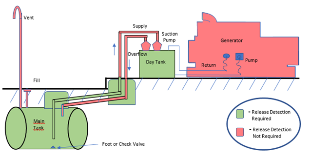
Drawing 3—Main fuel tank above day tank. Return piping from day tank to main tank (pressurized piping); underground supply piping from main tank (pressurized piping); vent and fill lines (nonoperational components).
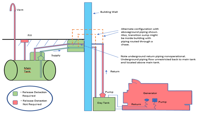
Drawing 4—Main fuel tank above day tank. Return piping from day tank to main tank (pressurized piping); underground supply piping from main tank (suction piping); vent and fill lines (nonoperational components).
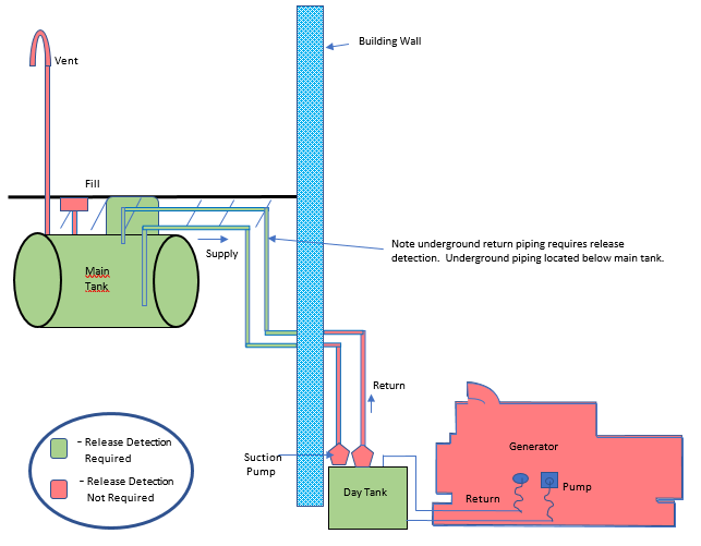
Complying With National Fire Protection Association 110 To Meet The Federal UST Regulation
Question: The National Fire Protection Association (NFPA), in NFPA 110: Standard for Emergency and Standby Power Systems, section 7.9.13, indicates that “automatically actuated valves shall not be permitted in the fuel oil supply or fuel oil return lines for Level 1 emergency power supply systems” (all other systems have no such restriction). This appears to restrict use of in-line mechanical and electronic line leak detectors, solenoid valves and other such valves in fuel oil supply and fuel oil return lines of emergency and standby power generators. NFPA 110 describes Level 1 emergency power supply systems as typically intended to automatically supply illumination or power, or both, to critical areas and equipment in the event of failure of the primary supply or in the event of danger to elements of a system intended to supply, distribute, and control power and illumination essential for safety to human life. How can owners and operators of EPG UST systems meet the pressurized piping release detection requirement for an automatic line leak detector in the federal UST regulation without installing a valve of any type in supply or return piping? (Added July 2020)
Answer: To comply with NFPA 110, valves such as line leak detectors and solenoid valves can be installed in fuel supply and return lines, if the provisions of NFPA 110, section 5.6.3.2, as noted below, are met.
In the 2015 federal UST regulation, EPA no longer deferred release detection for UST systems that store fuel for use by emergency power generators (EPGs). Owners and operators of these systems must meet release detection requirements. In 2016, NFPA revised NFPA 110. For EPG systems, pressurized underground piping, typically between the main tank and day tank must have an automatic line leak detector as part of meeting release detection requirements. For conventional in-line automatic line leak detectors to function properly, underground piping must be isolated from aboveground piping; lack of isolation causes false positive indications that leaks exist. You can achieve isolation by using a solenoid valve at a transition sump where the piping changes from underground to aboveground. With the solenoid valve in place, the automatic line leak detector tests the underground portion of the line.
EPA discussed with NFPA sections 7.9.13 and 5.6.3.2 of the revised NFPA 110 regarding use of line leak detectors and solenoid valves in pressurized piping. Section 7.9.13 is quoted in the question above. Section 5.6.3.2 indicates that “solenoid valves, where used, both in the fuel line from the supply or day tank closest to the generator set and in the water-cooling lines shall operate from battery voltage. Solenoid valves shall have a manual (nonelectric) operator, or a manual bypass valve shall be provided. The manual bypass valve shall be visible and accessible, and its purpose identified. The fuel bypass valve shall not be the valve used for malfunction or emergency shutdown.” Although these two provisions appear to conflict—one specifically allowing and one generally restricting the use of a valve in the fuel lines—EPA’s discussions with NFPA led us to conclude that for UST regulatory purposes of meeting the underground pressurized piping requirement, UST system owners and operators may rely on section 5.6.3.2, which specifically indicates that a solenoid valve is allowed.
NFPA standards only apply when jurisdictions incorporate the standards into a regulation. NFPA standards are typically incorporated into fire codes, including the International Fire Code. When owners and operators meet the federal UST requirement for pressurized piping release detection by installing a solenoid valve to isolate underground piping from aboveground piping and comply with NFPA 110, owners and operators must install a solenoid valve with a manual or nonelectric operator or a manual bypass valve. In addition, owners and operators should not use mechanical line leak detectors because they function by restricting product flow. EPA strongly recommends owners and operators use an electronic line leak detector that can sound an alarm instead of restricting or shutting off flow of product to the day tank.
Note that states’ requirements may be more stringent. Owners and operators should check with their state UST implementing agencies to determine applicable requirements.
Repairs to UST Systems
Repairs to Containment Sumps
Question: Does the National Leak Prevention Association/Ken Wilcox Associates, Inc. (NLPA/KWA) Standard 823 Standard for Preventative Maintenance, Repair and In-situ Construction of Petroleum Sumps meet federal UST regulatory requirements as an acceptable code of practice for containment sump repairs?
Answer: Yes. EPA recognizes NLPA/KWA Standard 823 as a code of practice developed by a nationally recognized association that addresses the requirements identified in 40 CFR § 280.33:
Regulatory Requirements (excerpt of pertinent portions of § 280.33(a) and (d))
Owners and operators of UST systems must ensure that repairs will prevent releases due to structural failure or corrosion as long as the UST system is used to store regulated substances. The repairs must meet the following requirements:
(a) Repairs to UST systems must be properly conducted in accordance with a code of practice developed by a nationally recognized association or an independent testing laboratory.
(d) Repairs to secondary containment areas of tanks and piping used for interstitial monitoring and to containment sumps used for interstitial monitoring of piping must have the secondary containment tested for tightness according to the manufacturer's instructions, a code of practice developed by a nationally recognized association or independent testing laboratory, or according to requirements established by the implementing agency within 30 days following the date of completion of the repair.
In particular, NLPA/KWA Standard 823 sets requirements for repairing sumps to prevent releases due to structural failure or corrosion by providing:
- Minimum criteria for qualifying a containment sump for repair
- Testing and performance requirements for materials used to
- seal containment sumps as a preventative maintenance or repair measure
- install or replace a sump entry fitting
- fabricate a new single wall or double wall sump using the existing sump as a fabrication mold
- Minimum requirements for installer certification and training by the equipment or material manufacturer
NLPA/KWA Standard 823 provides testing procedures at the conclusion of the repair for testing the sump for liquid tightness. Owners and operators must ensure that any repairs are made following all applicable steps in the standard, including post-repair testing for liquid tightness.
UST system owners and operators should check with their UST implementing agencies to determine state specific requirements, which may vary from EPA's determination.