Section 8: Ground Water Aquifers
All sections prior to this one have covered Hazard Ranking System (HRS) concepts that apply to all or most pathways. Beginning with Section 8, these concepts are applied to specific pathways as if documentation records were being prepared.
This section discusses issues surrounding aquifers, the basic unit of evaluation in the HRS ground water pathway. These concepts also apply to the ground water to surface water migration component of the HRS surface water pathway.
Aquifers are addressed individually in evaluating the ground water pathway. Thus, the general definition of "aquifer" for HRS purposes is crucial. In addition, precise descriptions of the aquifer of concern must be included in the HRS documentation record when evaluating the ground water pathway for a site. Such a description must include identification of the location of aquifers in relation to potential targets, the dimensions of the aquifers (deepness and thickness), and the extent of the aquifers (intervening layers, interconnections, and discontinuities). Once this description is in hand, the HRS analysis of the ground water pathway is relatively straight-forward.
The HRS evaluates each aquifer underlying the site separately. The highest scoring aquifer is selected as the aquifer of concern, and the HRS documentation record for the ground water pathway is prepared based on that aquifer: the score for that aquifer is the ground water pathway score. Identifying the highest scoring aquifer prior to scoring is usually infeasible because the likelihood of release and waste characteristics factor category values generally decrease with depth while the targets factor category value may increase with depth. Consideration should be given to including scores for each aquifer underlying a site in the HRS documentation record in order to facilitate responses to public comments.
8.1 Definitions
The term "aquifer" is not defined in the HRS, nor are several other key terms whose understanding is required in order to properly evaluate the ground water pathway. The following consolidated set of definitions is drawn from the HRS and the HRS Guidance Manual (Section 7.1):
- Aquifer: One or more strata of rock or sediment that is saturated and sufficiently permeable to yield economically significant quantities of water to wells or springs. An aquifer includes any geologic material that is currently used or could be used as a source of water (for drinking or other purposes) within the target distance limit (TDL). Note, this definition differs from many common definitions because it is based on the current or potential future use of the geologic material for drinking water or other purposes.
- Aquifer Boundary: A physical barrier to ground water flow identified as the contact between geologic materials defined as an aquifer and materials defined as non-aquifer (or as an aquifer but with a significantly lower hydraulic conductivity). Where aquifer interconnections are documented, aquifer boundaries are expanded to encompass the interconnected aquifers.
- Aquifer Discontinuity: An aquifer discontinuity occurs only when a geologic, topographic, or other structure or feature entirely transects an aquifer (or a single hydrologic unit) within the 4-mile target distance limit, thereby creating a continuous boundary to ground water flow within this limit. Aquifer discontinuities are a type of aquifer boundary. This concept will be discussed further below.
- Aquifer Interconnections: Subsurface conditions that allow two or more aquifers separated by aquifer boundaries to be combined into a single aquifer (i.e., a single hydrologic unit). Subsurface conditions must demonstrate that the aquifer boundaries separating the aquifers do not or would not impede the flow of ground water and hazardous substances between the aquifers. Aquifer interconnections are evaluated within two miles of sources at the site and in areas underlying contamination attributable to the site. This concept will be discussed below.
- Confining Layer: A layer of low hydraulic conductivity (relative to adjacent geologic materials) that is not expected to be used as an aquifer.
- Hydraulic Conductivity: The overall ability of water to flow through a geologic material, accounting for all openings in the material (e.g., between grains, through fractures, along lava tubes). For HRS purposes, the terms hydraulic conductivity and permeability are used interchangeably.
- Layer of Lower Relative Hydraulic Conductivity: A geologic material with lower hydraulic conductivity than adjacent geologic materials. If used to establish aquifer boundaries, the difference in hydraulic conductivity should be at least two orders of magnitude.
- Single Hydrologic Unit: The combination of geologic materials and aquifers that are determined to be within the same aquifer boundaries, including all interconnected aquifers.
- Target Distance Limit (TDL): Maximum distance over which targets for the site are evaluated. The target distance limit varies by HRS pathway.
8.2 Identifying and Evaluating Aquifers
The first step in scoring the ground water pathway is to identify the geological materials being used as aquifers within the target distance limit. An understanding of these materials can be gained from a geological cross-section of the site.
- Aquifer Identification
- Aquifer Boundaries
- Aquifer Discontinuities
- Aquifer Interconnections
- Karst Terrain and Aquifers

If a geologic cross-section is not already available, one should be created. Such a diagram is an invaluable tool in understanding the ground water pathway at a site. It can be useful in evaluating factors such as observed releases, actual contamination, depth to aquifer, travel time, hazardous substance mobility, and assigning target populations to aquifers. The diagram should distinguish among the various geological materials by identifying:
- materials that meet the definition of aquifer;
- aquifer boundaries, interconnections, and discontinuities; and
- aquifers combined for scoring purposes into single hydrologic units.
The basic geologic cross-section should be included as part of the site inspection report. The cross-section, modified for scoring purposes as indicated above, should be included in the HRS documentation record. The Regional QC Guidance Manual provides details on the recommended content and format of geologic cross-sections.
Once the geologic units are defined, a determination of which ones are aquifers must be made. As indicated in the HRS Guidance Manual definition (see above), the unit must be "saturated and sufficiently permeable to yield economically significant quantities of water to wells or springs." The principal information sources for making such determinations include:
- visual surveys during site visits;
- USGS topographic maps (verified by site visits);
- well logs from current and past well installations; and
- county records of well installation and ground water use.
Because the definition includes units that are "currently used or could be used" for any economic purpose, State ground water classifications are also useful, particularly in determining whether a unit might be used in the future. Comprehensive documentation of the rationale for determining that a unit is an aquifer is essential and must be included in the HRS documentation record.
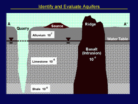
The above illustration shows four hydrologic units underlying the source: alluvium, limestone, shale, and the basalt intrusion. The hydraulic conductivity (in centimeters per second or cm/s) is provided for each unit. Assume for purposes of this example, that data are available documenting that the first three of these units are aquifers.
The uppermost aquifer consists of the alluvium (or the "alluvial aquifer"). Since there is no layer between the surface and the alluvium, the alluvial aquifer is not bounded above. Based on the 100-fold difference in hydraulic conductivity, the alluvial aquifer is bounded below by the limestone unit. Similarly, the alluvial aquifer is bounded on the right by the basalt intrusion (due to its complete transection of the unit and its 1,000-fold difference in hydraulic conductivity). Since the HRS Guidance Manual indicates that quarries and quarry water are "non-aquifer materials," and the quarry completely transects this unit, the alluvial aquifer is bounded on the right by the quarry.
For the same reasons, the limestone aquifer is bounded:
- above by the alluvial aquifer;
- below by the shale;
- to the right by the basalt intrusion; and
- to the left by the quarry.
The boundaries of the shale aquifer are not the same. Specifically, this unit is not bounded on the right because the quarry does not completely transect the shale unit. In principal, it is bounded below only by its lower confining layer (e.g., bedrock; not illustrated). It is bounded above by the limestone aquifer and to the right by the basalt intrusion.
The key concepts illustrated here are that (1) aquifer boundaries are defined first in terms of relative hydraulic conductivity and (2) potential aquifer discontinuities must completely transect an aquifer in order to form a boundary.
As illustrated above, aquifer discontinuities are frequently essential in determining aquifer boundaries. Thus, the presence or absence of discontinuities may have a significant affect on an HRS ground water pathway score.
The criteria for determining that a structure or feature constitutes an aquifer discontinuity is specified in the HRS rule (Section 3.0.1.2.2). To paraphrase, the structure or feature must completely transect the aquifer so as to form a continuous barrier to ground water flow. Consistent with other HRS Guidance definitions, changes in hydraulic conductivity of 100-fold or greater and areas of contact between aquifer and non-Aquifer materials are considered as barriers to ground water flow.
Examples of discontinuities include:
- Major offset faults;
- Intrusive formations (dikes and sills);
- Erosion channels (e.g., rivers and streams); and
- Salt water interfaces.
See Highlight 7-14 of the HRS Guidance Manual illustrates a salt water aquifer discontinuity.

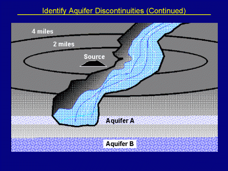
Even if aquifers are apparently separated by distinct boundaries or discontinuities,they can sometimes be combined into a single hydrological unit if an interconnection exists. An interconnection occurs between aquifers whenever the nature of the intervening materials allows for transfer of ground water and hazardous substances with minimal or no disruption in flow path or velocity. Interconnections must be within two miles of the sources or within areas of observed ground water contamination that extend beyond two miles from the sources.
Just as in evaluating aquifer discontinuities, if evidence is not available to establish aquifer interconnections, then it cannot be assumed that such an interconnection exists. If such is the case, each aquifer is evaluated as separate hydrologic units.
The presence of karst terrain and its implications for aquifer transport characteristics warrant special consideration in HRS evaluations. The HRS Rule (p. 51586) defines karst terrain as: "Terrain with characteristics of relief and drainage arising from a high degree of rock solubility in natural waters." "Karst" refers to a characteristic of a geologic material or formation resulting from the dissolution of the formation by natural waters over time. The majority of karst occurs in limestones, but karst may also form in dolomite, gypsum, and salt deposits. Features associated with karst terrains typically include irregular topography, sinkholes, vertical shafts, abrupt ridges, caverns, abundant springs, and/or disappearing streams. Karst aquifers are aquifers associated with karst terrain and consist of dissolution cavities and the channels. As such, the movement of hazardous substances released into karst aquifers is highly unpredictable, and transport over relatively long distances can occur very rapidly.
The HRS includes special provisions for evaluating several factors for karst aquifers:
- Potential to Release
- Depth of aquifer
- Travel time
- Waste Characteristics
- Mobility
- Targets
- Nearest well
- Population/potential contamination
Navigate to another section of the course:
| Table of Contents | |||||||||
|---|---|---|---|---|---|---|---|---|---|
| 1 | 2 | 3 | 4 | 5 | 6 | 7 | 8 | 9 | 10 |
| 11 | 12 | 13 | 14 | 15 | 16 | 17 | 18 | 19 | 20 |
